Inductor size
The energy stored in an inductor and therefore the core size is a function of the inductance (=1/2 LI^2). The output filter on a class D amp can be considered to be a low-pass filter at around 40KHz (> 20KHz) vs a wolfer low-pass at say 200Hz. That's a ratio of 200/1, ie the passive crossover needs an inductor about 200 times bigger than the amp filter, since they are carrying the ~same current.
Can someone explain me why the output filters of most class D boards consist of smd inductors and capacitors while if the amp is followed up by an analog crossover, the coils and caps used there are absolutely enormous in comparison.
Are the output filters just under spec'd with cheap class D boards, or is the average DIY'ers analog crossover network just overkill?
The energy stored in an inductor and therefore the core size is a function of the inductance (=1/2 LI^2). The output filter on a class D amp can be considered to be a low-pass filter at around 40KHz (> 20KHz) vs a wolfer low-pass at say 200Hz. That's a ratio of 200/1, ie the passive crossover needs an inductor about 200 times bigger than the amp filter, since they are carrying the ~same current.
What do you have in mind? Pulse transformers have been used to drive FETs (etc) in PWM applications, especially where high voltages are present. There is a technique where a series FET is used to store the gate pulses because, of course, transformers do not couple DC. Pulse transformers do not couple audio frequencies either. And, also of course, there is no point in using a high frequency transformer on the output. By design, the FETs see a very high impedance at the switching frequency that the output filter input choke provides, and passes, ideally, only audio frequencies. As the FET totem pole switches +Vcc and -Vdd, the output choke charges and discharges slightly about the audio signal current value. The FET conducting less than 50% duty cycle is actually dumping current back into the supply as the output choke discharges.
Pulse transformers are bad for audio class D, because of switching get not as good with it, for smsp with 1 uS deadtime this is not such a problem
Yes good question, busy with cnc system pcb now, I have also a thread with class d, but is also not active now, to busy.
To contribute . I want to argue the dual mosfet buffer are uselless in half bridge class d . The reference voltage for both high side and low side are different .
Also , i have class d circuit ucd one .which when start up got constant voltage at the high side mosfet for almost 10ms . That can damage a mosfet . My question is what cause it .
Also , i have class d circuit ucd one .which when start up got constant voltage at the high side mosfet for almost 10ms . That can damage a mosfet . My question is what cause it .
Maybe when start up it does not oscillate directly staying on higher voltage for short MS time, can be negative side or positive side, in different systems.
regards
regards
https://guitar.com/features/interviews/amp-tech-colleen-fazio-analogue-digital-amps/
Clickbait title but she mentions the poor repairability of class-D as its drawback.
What do you guys say?
Clickbait title but she mentions the poor repairability of class-D as its drawback.
What do you guys say?
tubes are so forgiving when making design mistakes, solid state is not forgiving at all, and that could explain the analog preferences.
The problem is the same as other technology. ie. People with the skill to rejuvenate old products couldn't be bothered. It goes into the recycle bin. Some old amps are repaired because they are art, but most are just junk.https://guitar.com/features/interviews/amp-tech-colleen-fazio-analogue-digital-amps/
Clickbait title but she mentions the poor repairability of class-D as its drawback.
What do you guys say?
Class d is not for diy . Failure rate is very high . 2 layer or 4 layer pcb . With smd components carefully placed on a smallest board posssible can give just enough quality . Its more corporate friendly . 🙃
Course it is, and yes with fast dv/dt we need carefully designed pcb,s. But in these days diy people are quite good in designing this, 4 layers is not needed, only with Gan we have to consider but not now it is also here needed., I am even busy make a test version on normal test board, and yes maybe it fails. So I use low switching for test.Class d is not for diy . Failure rate is very high . 2 layer or 4 layer pcb . With smd components carefully placed on a smallest board possible can give just enough quality . Its more corporate friendly . 🙃
I have look also at some designs like ice-power, I do see it is patented, but technology is already known before that.
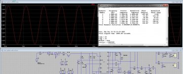
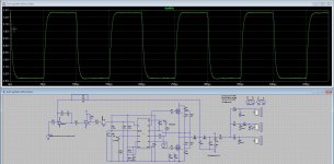
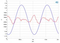
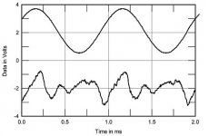
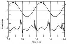
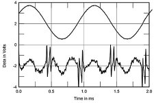
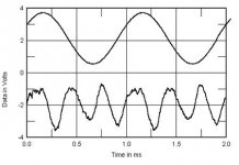
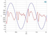
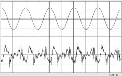
Here some tests, see the square tests, with three way speaker connected and open output, the feedback does quite good with pole set above switching, there it does control quite oke, even with open output, now using this as a front end, I can design further for lowest distortions, unfortunately both stability and distortion impact stability so need some compromises. Did see a high pass filter does correct quite nice for low pass lead purposes. Design has a faseshift oscillation system, and with a pole setting high there is no lead for low pass, only there is a zero present with no pole.
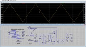
Pics let see results, with square 10 Khz, with speaker load (three way) and open, + result of triangle on input and see how nice it is on the output in 8 ohm resistor. first pic distortions look low. All is included with dead-time on highest setting UC 20124 chip..
have a nice new year all here, and much pleasure making things.
regards
Attachments

Last edited:
Until now I haven't heard any power amp in this technology without unpleasant reproduction characteristics in the treble range (e. g. "ssss" distortions) despite the fact that the values for THD+N are extremely small. Until recently no one could give me an explanation for this while each listening tests with class D amplifiers.
Now I know exactly what the reason is therefore - check out in this case the curvatures for distortion character (fundamental notched out) of various class-A and class AB power-amplifiers, reviewed in the magazine Stereophile - go to post #2 under
https://www.diyaudio.com/community/...st-possible-thd-n-really-the-best-way.367692/
in the attached files here you will find basically the same diagrams, but only class D power amps - also reviewed by Stereophile (best results seems to be get from the Yamaha).
The question for me is, whether it is possible to obtain the same distortion character (sine wave, clean H2/H3) as with tube or class A solid state power amplifiers like Graaf GM200 or Pass Aleph 4 (as showed in the previous mentioned URL) through an optimized design. or is it an inherent/intrinsic distortion effect due the still present switch mode on all class-D amplifiers.
Maybe a high order low pass filter in very good design provide a distortion character as to find in the Stereophile reviews of Pass Aleph series or some tube power amps like Lamm Industries, Graaf, Jadis etc. - that would be interesting to know.
Attachments
-
 Bel Canto e.One Ref600M Hypex UcD.jpg105.1 KB · Views: 325
 -
 Bel Canto Ref1000M IcePower.jpg18.3 KB · Views: 313
 -
 Sonic Impact Model TA2024 +sixth order low pass filter unit.jpg19.9 KB · Views: 305
 -
 Sonic Impact Model TA2024.jpg21.8 KB · Views: 319
 -
 Yamaha MX-D1.jpg18.7 KB · Views: 299
 -
 Channel Island Audio D-100.jpg16.2 KB · Views: 324
 -
 Audio Alchemy Hypex UcD.jpg29.5 KB · Views: 311
 -
 Primare Hypex UcD.jpg36.6 KB · Views: 326
Last edited:

I can say to try the Phillips ucd who has no op amps, if these are do ss sound in tremble. I convinced that
good op amps are needed, and some need to be fast to, like for pré feedback, but these can sound bright in tremble
because if the speed she have, burr brown have nice sound are much used in high end equipment.
Do not forget class D is a modulating system who is not linear, most because of mosfet shortcomings, Gan is much o better
but less easily to work with.
I am busy with look at this system, simulating and such.
I also want to argue lot of discrete design tend to cut at 40khz whereas clas ab amplifier go beyond 100khz . Hf with high amplitude will suffer losses . Producing. Lot of I'll effect . Chips class d tent to overcame this lot of them have very high bandwidth . Almost of class ab . At hf h amplitude it will became triangle wave due to slewrate .
... mean you "due to limited slew rate" ?I also want to argue lot of discrete design tend to cut at 40khz whereas class ab amplifier go beyond 100khz . Hf with high amplitude will suffer losses . Producing. Lot of I'll effect . Chips class d tent to overcame this lot of them have very high bandwidth . Almost of class ab . At hf h amplitude it will became triangle wave due to slew rate .
As I know triangle wave instead sine wave for distortion character on analog amps I get only in cases, if inside of a NFB loop are two gain stages and a so called C-dom (around 22-100pF) is in use. This capacitor create no low pass filter but a converter from sine wave to triangle wave (very audible, if you increase the value to 10-47nF).
The Sharp SM-SX100 looks quite good despite the age - go to post #16 under
https://www.diyaudio.com/community/...ded-class-d-amplifier-overview-wanted.271519/What is here very special (in opposite to most used class D approaches) ?
I have heard it on High End exhibition 2001 (Gravenbruch Kempinski/Frankfurt) and was impressed about the sonic quality at those day.
In this model with Class-D technology, the diagram of distortion character (fundamental notched out) really looks like from a Class-A amplifier:
LKV Veros PWR+ - go to Fig. 8 under
https://www.stereophile.com/content/lkv-veros-pwr-power-amplifier-measurementsfound under
https://www.audiosciencereview.com/...oined-bruno-putzeys-class-d-revolution.15489/How did one do that?
LKV Veros PWR+ - go to Fig. 8 under
https://www.stereophile.com/content/lkv-veros-pwr-power-amplifier-measurementsfound under
https://www.audiosciencereview.com/...oined-bruno-putzeys-class-d-revolution.15489/How did one do that?
I ask Mr. Bruno Putzeys concerning the issues mentioned in post #192 and he send me this statement in his reply:
Actually the effect you’re mentioning is solved by removing the hysteresis distortion that the output inductor (which all class D amplifiers have). I would suggest trying the Purifi Eigentakt modules - go to
https://purifi-audio.com/eigentakt
which were explicitly designed to address this problem. They sound very “sweet” in the top end.
But now the following question rises up:
Why aren't inductors used in each output filter of class-D amplifier units that don't have these disadvantages ?
What kind of inductors are in use of the modules of Purifi Audio and the mentioned amp (with modules from purifi audio) in my previous post #196 ?
https://www.soundimports.eu/de/purifi-1et400a.htmlThe whole review is here
https://www.stereophile.com/content/lkv-veros-pwr-power-amplifier
Last edited:
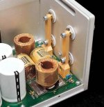
Inductors always have disadvantages. Any Magnetic material (like iron) used in the core of the inductor will have some hystersis. Using the magnetic core allows high inductance in a small space & low I^2R (resistance) power losses. One could use air core inductor, but it will be larger & the inductor magnetic field is more difficult to isolate and shield. The inductor cores in the Purifi amplifier have a closed magnetic circuit so the field stays mostly contained."....Why aren't inductors used in each output filter of class-D amplifier units that don't have these disadvantages ?
What kind of inductors are in use of the modules of Purifi Audio and the mentioned amp (with modules from purifi audio) in my previous post #196 ?...."
>> The secret sauce of the Purifi amplifier is the very high loop gain and feedback gain used, with a carefully designed stable feedback network. <<
Read the blogs from Purifi: https://purifi-audio.com/blog/
"May 13, 2020 - Our blog post concerning hysteresis distortion got people asking what secret non-hysteretic material we were using then."
Combating Hysteresis Distortion (part 1: Amplifiers) read more
"Apr 28, 2020 - Read any Purifi interview and someone is sure to mention hysteresis distortion (or iron distortion, same thing)"
This Thing We Have About Hysteresis Distortion read more
Some Purifi patents discussing the large loop gain and carefully designed feedback method of implementation;
Amplifier circuit: US20200389135A1
Amplifier with an at least second order filter in the control loop: US20200382084A1
Amplifier with a compensator with a network of at least third order: US11082017B2
The TacT Millennium uses such inductors from Jensen without ferrite core (air coil):Inductors always have disadvantages. Any Magnetic material (like iron) used in the core of the inductor will have some hystersis. Using the magnetic core allows high inductance in a small space & low I^2R (resistance) power losses.
One could use air core inductor, but it will be larger & the inductor magnetic field is more difficult to isolate and shield. The inductor cores in the Purifi amplifier have a closed magnetic circuit so the field stays mostly contained.
http://www.jantzen-audio.com/wax-coil/go to the attached photo
Attachments
So what is the resonant frequency of those inductors? I don't see the specification.The TacT Millennium uses such inductors from Jensen without ferrite core (air coil):
http://www.jantzen-audio.com/wax-coil/go to the attached photo
- Home
- Amplifiers
- Class D
- Class D Design Issues