Hi there!
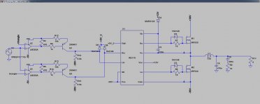
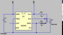
I'm trying to build a Class D amplifier using a 555 triangle generator, LM393AP comparator and IR2110 mosfet driver.
The problem is that I have very high offset voltage.
Below is the schematic and the outsignal and the DC offset (in blue).
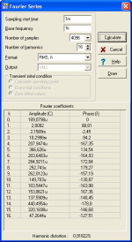
"Fourier components of V(out)
DC component:-2.47381
"
I'm trying to build a Class D amplifier using a 555 triangle generator, LM393AP comparator and IR2110 mosfet driver.
The problem is that I have very high offset voltage.
Below is the schematic and the outsignal and the DC offset (in blue).
"Fourier components of V(out)
DC component:-2.47381
"
Attachments
Last edited:
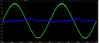
What shape is your triangle? If not perfectly symmetrical, it will do odd things in particular offset problems.
I'm using a 555 to generate my triangle, so it is exponential, not perfect. I'll try to simulate using a perfect triangle.
That was it I think. I used a perfect triangle generator and got "DC component:-0.0217712".
Thank you @JonSnellElectronic
That was it I think. I used a perfect triangle generator and got "DC component:-0.0217712".
Thank you @JonSnellElectronic
Last edited:
The shape is less important in offset. It can be exponential, but no DC component is allowed. If there is DC, you will have offset.
The shape is less important in offset. It can be exponential, but no DC component is allowed. If there is DC, you will have offset.
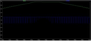
Here is the output from the 555. The offset is only 0.02V.
When I use a perfect triangle (ideal) I have no offset problem.
I'll try using a triangle generator with two op-amp, or 555 and integrator.
Attachments
Last edited:
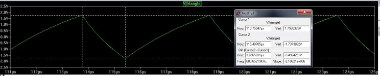
If the upper and lower waveform is not identical in shape, the centre point will be uneven causing a DC offset. The upper and lower pulse widths must be the same.The shape is less important in offset. It can be exponential, but no DC component is allowed. If there is DC, you will have offset.
If the upper and lower waveform is not identical in shape, the centre point will be uneven causing a DC offset. The upper and lower pulse widths must be the same.
As you can see in the picture from the post above the upper and lower waveform have different widths. I thought this was the problem. I kinda fixed it using some diodes, but now the offset is still here (a bit smaller).
"DC component:-2.00844"
Attachments
For the first time duty cycle were asymmetric, now the amplitudes. You could show where the problem is (schematic of triangle generator).
No need for diode, all needed is a TLC555, a capacitor, and a resistor from the output to the capacitor.
No need for diode, all needed is a TLC555, a capacitor, and a resistor from the output to the capacitor.
Here is the triangle generator circuit. I'm trying the one you posted now. Looks good.
PS. What simulation software is that?
PS. What simulation software is that?
Attachments
Last edited:
That is it. Works great. Thank you!
The only problem is that I have to set the input voltage to have a peak of about 0.7V, but it may have to do with the width of PWM, maybe it doesn't like above 80% duty cycle or something.
DC component:-0.0178523
Total Harmonic Distortion: 0.806305%
The only problem is that I have to set the input voltage to have a peak of about 0.7V, but it may have to do with the width of PWM, maybe it doesn't like above 80% duty cycle or something.
DC component:-0.0178523
Total Harmonic Distortion: 0.806305%
Youre welcome!
I use Tina TI. Thank you
I dont understand "the problem", nor the "to do".
When the input sinusoidal signal is set to 0.7V amplitude, i have 0.8% THD, when the input signal is set to 1.41V amplitude (1V RMS) i have about 4& THD, but I guess this is normal.
Also, another question. On the input what do you suggest adding apart from a low pass filter? (R = 2.2k, C = 1n, the cutoff frequency is about ~ 70khz)
Last edited:
4% THD is not normal, at least not because of the modulator. But I dont know your settings. Probably the freq is too high.
High pass filter is also needed. And later a closed loop control.
High pass filter is also needed. And later a closed loop control.
Maybe the simulation model of the IR2110 is not precise either? Or the speed of the comparator.
Even if it is not good practice, I think I will leave my schematic open loop, for my first version. I want to build it and scope it.
For a simple protection, would two fuses on each power supply branch be enough? Rated at 8-10A.
Even if it is not good practice, I think I will leave my schematic open loop, for my first version. I want to build it and scope it.
For a simple protection, would two fuses on each power supply branch be enough? Rated at 8-10A.
Last edited:
Anything can be problematic in a simulation, including simulation method. If you provided full information we had a chance to find the problem. As youve seen the problem is often in the parts you don't show at all.
Fuse is good for preventing fire and protecting tracks, but not for semiconductors. A much smaller fuse may protect your speaker from the probably event when output shorted to supply rail.
Experimenting with an open loop design is very good.
Fuse is good for preventing fire and protecting tracks, but not for semiconductors. A much smaller fuse may protect your speaker from the probably event when output shorted to supply rail.
Experimenting with an open loop design is very good.
If it was referenced to ground I don't think the circuit would have worked. +12V and +5V_2 are referenced to -30V."+12V"
What is the reference for this voltage? I hope not GND!
Sorry, I thought the rest of the circuit was not neccesary.
Here it is in full.
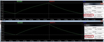
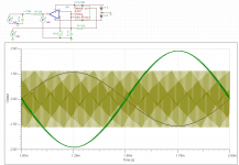
After changing the frequency a bit and the gate resistor for mosfets (they were 47ohms, now they are at 4.7ohms) I get 3% THD (the smaller the input signal the better the THD). I think the culprit is the slow LM393A and other delays, this is also why the circuit clips at about an input voltage of ~1.5V. In the second image, the blue track is the output from one of the op-amps. Input voltage peak 1.6V.
Attachments

I just finished the build and it isn't working yet.
When i measure the output of the LM7805 it is at +10V, instead of +5V (in reference to -30V). What could cause this? The LM7805 is not fake.
Nevermind, it is ok. I think it is because the HIGH is stuck to high. I still get no output. I get triangle output from the 555, now checking the LM393.
I have a very high offset on the input signal after the C2 capacitor (i replaced him with a polypropeline one, WIMA, 1uF).
Attachments
Last edited:
I am having a problem with the LM393. It has a very high input offset where the signal should be. I used two 100n capacitors in addition to those on the schematic on the V+ and V- of the comparator. Any other thoughts?
Nevermind this, I just grounded the input and the output is a rectangular signal, ok. The problem si that the IR2110 doesn't output anything, even though HIN and LIN are ok. I think it has to do with the VDD (the output of the LM7805) being 10V and not 5V.
Is this because it adds +5V from LM7805 and +5V from the 5V rail, through the 1N4148 diode at the level shift?
Last edited:
- Status
- Not open for further replies.
- Home
- Amplifiers
- Class D
- Class D amplifier - Very high DC offset voltage