There was a problem with the LM7805.
It's all good now.
Another problem now is the input stage. I have some very high noise when the input filters are connected (capacitor in series and capacitor to ground) and the output stays high and it burns my mosfets.
It's all good now.
Another problem now is the input stage. I have some very high noise when the input filters are connected (capacitor in series and capacitor to ground) and the output stays high and it burns my mosfets.
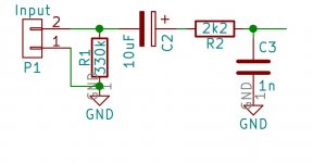
Unfortunately I can't view your pdf on mobile. Do you have resistor from input of comparator to gnd?
The amplifier is working great if I ignore the input capacitor (I tried also 10uF polarised and 1uF non polarised).
This is the order of the input block : Signal -> resistor to ground -> capacitor series - > resistor in series -> capacitor to ground.
It is a high pass filter followed by a low pass filter. The "capacitor series" is the problem, without it it works great. Just a small hiss, but that is because I used NE555 and not LMC555. I measured with the oscilloscope the triangle output and it has a frequency of only 144KHz, not 200KHz. I will try to use a LMC555 to see if that changes.
Attachments
Last edited:
Oups, my bad. You are right.
Also, the reason why I only have 140KHz at the output i that i used the LM555 instead of the CMOS relative, LMC555? Could there be any other problem?
Apart from this, the circuit is working fine. After about 15 minutes of music at half volume the transistors are just warm. I used IRF640N which are worse than 540N as they have higher Rds-on. I think with IRF540N the results will be much better.
LMC555 (or TLC555) is better indeed, however Im not sure if the noise is caused by LM555.
In any time there are many possibilities to generate noise. Try changing 1 thing at a time!
IRF540Z is even better.
In any time there are many possibilities to generate noise. Try changing 1 thing at a time!
IRF540Z is even better.
My bad, the noise wasn't the 144KHz, you cannot even hear that.
The noise is approximate the same with the mains frequency (50Hz) and it gets worse when I connect the cable audio cable and leave it floating.
Maybe the transformer (toroidal) is the culprit? Or do I have a ground loop on the PCB?
The output at 1KHz is looking nice and clean. I get a peak voltage of about 20.4 volts using the laptop as a signal generator (1Vpp). I'm happy with that. (except the mains noise)
Last edited:
Every amplifier has mains noise if you connect a cable to the input and leave floating, since it is capacitively coupled to the environment. You can reduce it by properly shielding both the amplifer and the input cable. (And/or of course by connecting the source, or shorting inputs.) The ground loop is an other, not that trivial way to receive hum (mains induced noise), but it behaves very differently from what you described. Generally both mechanisms work at the same time, but one is stronger than the other.
Last edited:
- Status
- Not open for further replies.
- Home
- Amplifiers
- Class D
- Class D amplifier - Very high DC offset voltage