I will try psu, what about 3x2700uF 160V caps half the price of one 4700 200V cap?
Great work on PCBs!

I also like coupling many capacitors than having just a big one. Also it helps to reduces ESR of capacitors especially in SMPS
I have no idea about which materiel of toroid is used for the output inductor here. I think T106-2 would not work for D2000 so what are you going to use?
Last edited:
I will try psu, what about 3x2700uF 160V caps half the price of one 4700 200V cap?
Use 2x2200uF/160V instead 4700uF/200V.
Great work on PCBs!
I also like coupling many capacitors than having just a big one. Also it helps to reduces ESR of capacitors especially in SMPS
I have no idea about which materiel of toroid is used for the output inductor here. I think T106-2 would not work for D2000 so what are you going to use?
T200-2, T225-2, T300-2... cores are available
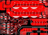
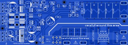
I've made psu layout, nothing fancy, anyone willing to check? I will post sprint file too when it has a go.
Also included softstart, I designed it some time ago and worked, I don't remember exactly schematic. It's resetting on power loss.Or should do.
Amplifier board could fit T200 if output filter cap is shifted 90 degrees and moved in right corner, and coil centered between side caps. I'm not going to build this amp, i made it for good practice, so don't ask what i'm going to use😉
Attachments
I've made psu layout, nothing fancy, anyone willing to check? I will post sprint file too when it has a go.
Also included softstart, I designed it some time ago and worked, I don't remember exactly schematic. It's resetting on power loss.Or should do.
Amplifier board could fit T200 if output filter cap is shifted 90 degrees and moved in right corner, and coil centered between side caps. I'm not going to build this amp, i made it for good practice, so don't ask what i'm going to use😉
Nice pcb, thank you.
Regards
I've made psu layout, nothing fancy, anyone willing to check? I will post sprint file too when it has a go.
Also included softstart, I designed it some time ago and worked, I don't remember exactly schematic. It's resetting on power loss.Or should do.
Amplifier board could fit T200 if output filter cap is shifted 90 degrees and moved in right corner, and coil centered between side caps. I'm not going to build this amp, i made it for good practice, so don't ask what i'm going to use😉
Nice work c08bm
PC816 it's single led, so...
I wonder what if one igbt shorts, should't a triac be around?
PC816 is for over current protect, you need triac for DC protect.
Yes, but it's single led, on schematic there is dual antiparalel led opto.
Sprint file with both psu and amp uploaded.
Thanks for sharing your work. I'm just interested only the O/C protection circuit board separated from the power supply which anybody can use a different power supply and to power up the amp along with the protection. If you can make it for us easily, please do.
Thanks and best regards.
Lycanlk
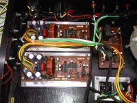
apex d200 for my home
sound is hifi
sound is hifi
Attachments
Last edited:
Off-topic
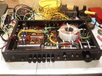
Sorry for this off topic post because I hope someone can help me to fix this amp. Its form a JBL subwoofer module which gives a hum like a siren horn. When I give a signal the output is not clear and very cracky. oscillate at 77KHz at +/- 50v. It normally runs +/- 65V which gives higher frequency but both results the same issue. Anybody can help me out?
Thank you,
Lycanlk
Attachments
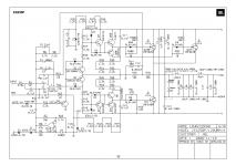
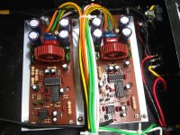
I think i've spoted some mistakes on the left LM311:
out(7) is not connected to emiter 5401,
missing connection left LM311 IN-(3) to OUT2(7) of right mc33078,
pins inverted on schematic, OUT2(7) of U1B it's connected to IN+ of LM311(2) but shows pin 3, and IN- (3) show 2, so maybe connections wrong, mr, Mile could tell us.
Good job for first try, keep practice, use zone instead of track when you want to fill area, route tracks between pins and can ditch straps
- Home
- Amplifiers
- Class D
- Class D Amp with LM566, LM393 and 2XIRF530