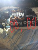
Hey guys i have a US audio m5150 mono block amplifier. It's the same board in the lanzar opti 7000k
The Amp is working however when you power up the Amp and attach a load to the output (to wake up the output) this resistor gets awful hot!! Also if u play a small load on the amplifier the output transformers get extreamly hot. Now this resistor is reading as shorted.
The amplifier was repaired from a constant in protect mode and chip ir2113 was replaced. Now amp works however gets extreamly hot for no reason.
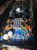
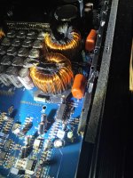
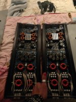
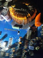
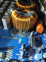
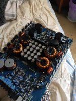
I'll attach a few pics of what parts I'm talking about.
I plan on replacing the resistor but as I don't have a schematic I can't really test other components.
Red circle is the replaced driver chip ir2113
Green circle is of the resistor that gets awful hot as soon as the output is activated.
I might add no other resistors near any of the other drivers or transformers gets hot. It's only the one resistor but all 4 transformers get extreamly hot
(just having trouble uploading photos)
Last edited:
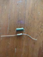
*update. I pulled the resistor out of the cricut and it tests fine 15k ohms. So if the ir2113 is OK. And the resistor is OK then why is it getting so hot?
From the pictures you posted it looks like you may have a shorted output inductor
The inductor in question sits right in front of the resistor that gets hot .
The inductor in question sits right in front of the resistor that gets hot .
From the pictures you posted it looks like you may have a shorted output inductor
The inductor in question sits right in front of the resistor that gets hot .
HI. That black stuff is just glue. But how would I check to see if it's shorted?
Attachments
That resistor may be a resistor that's across the rail to discharge the rail caps. If so, it will get hot as soon as the power supply switches on.
The inductors in many amps are made to order by bean counters and therefore the cheapest possible. Fewer turns of copper and cheaper cores will make the inductors run hot. It's possible but unlikely to have 4 defective inductors.
The inductors in many amps are made to order by bean counters and therefore the cheapest possible. Fewer turns of copper and cheaper cores will make the inductors run hot. It's possible but unlikely to have 4 defective inductors.
HI perry. I have 2 of these amplifiers and if I check the other one that resistor in circuit reads ohms. Also on the other side of the board of the faulty amp that resistor also reads. It's only this 1 resistor that is shorted in circuit and normal out of circuit.That resistor may be a resistor that's across the rail to discharge the rail caps. If so, it will get hot as soon as the power supply switches on.
The inductors in many amps are made to order by bean counters and therefore the cheapest possible. Fewer turns of copper and cheaper cores will make the inductors run hot. It's possible but unlikely to have 4 defective inductors.
The Amp was working perfectly fine before the driver chip let go.
No other resistors around the inductors gets hot. Only this 1.
But all the inductors along with this resistor get HOT and I mean burn you're hand hot. But amp works fine?
I can't trace very far from that resistor as the trace goes under the inductor and a bunch of glue.
I may add all this heat comes from simply activating the output by putting a 4ohm load on it. On a 20a power supply. Not playing any music
This board comes apart into 2 pieces. So at the moment just the output side is out.
Attachments
Last edited:
Did you fix the fault that caused the failure of the 2113? If so what was the problem and how was it repaired?
Have you checked the mosfets ?
The ir2113 is just a gate driver.
Yes they all check out fine. As I said the Amp now works fine and puts out a clean signal on the output. Does not draw too much current it just is running extremely hot. And u can smell burning as a result.
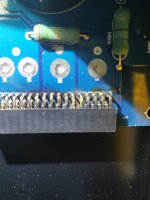
What caused all this mess was a slip of a multimeter probe where the power supply joins to the output. You can kind of see where they slipped pins are a bit distorted.
I found why it was cycling between power and protect. Was ir2113. Replaced that. But now having heat problems.
Attachments
I got some new 15k resistors to replace the one that was running hot. However my local store only had 1w resistors they are not quiet as big as the original. Will this work for testing purposes or should I put 2 in parallel?
Why do you think the resistors need to be replaced?
Don't power it up without the 22 ohm resistor.
Don't power it up without the 22 ohm resistor.
Last edited:
Why do you think the resistors need to be replaced?
It got extremely hot. And also one 22ohm resistor I must have accidentally broke when I was taking the heat sink clips off. It could have been broken previously I'm not sure.
Edit. Sorry I don't think I need to replace the 15k resistor that's getting really hot it checked out fine out of circuit.
But I will need to replace the broken 22ohm one of the legs were snapped off it was mounted vertical on the board
Attachments
Last edited:
Did you check to see if it was connected across one of the rails as was previously suggested?
Not sure how to do that? I don't have a schematic.
You should be able to read 0 ohms from the center leg of the rectifiers to the input legs of the rectifiers.
There should be an identical resistor for the other rail as well.
Contact Lanzar to see if they will send you the diagram.
There should be an identical resistor for the other rail as well.
Contact Lanzar to see if they will send you the diagram.
You should be able to read 0 ohms from the center leg of the rectifiers to the input legs of the rectifiers.
There should be an identical resistor for the other rail as well.
Contact Lanzar to see if they will send you the diagram.
I get a direct short between the legs on the left(in photo) on the mosfets circled too one side of the resistor getting hot
Attachments
I think that that resistor is as was thought and will get hot. It's large so that it can dissipate enough heat without overheating/burning.
I think that that resistor is as was thought and will get hot. It's large so that it can dissipate enough heat without overheating/burning.
It's not only that resistor that gets hot. All the output inductors get burning hot. And the resistor on the other side stays nice and cool?
- Home
- General Interest
- Car Audio
- Class d amp repair help.
