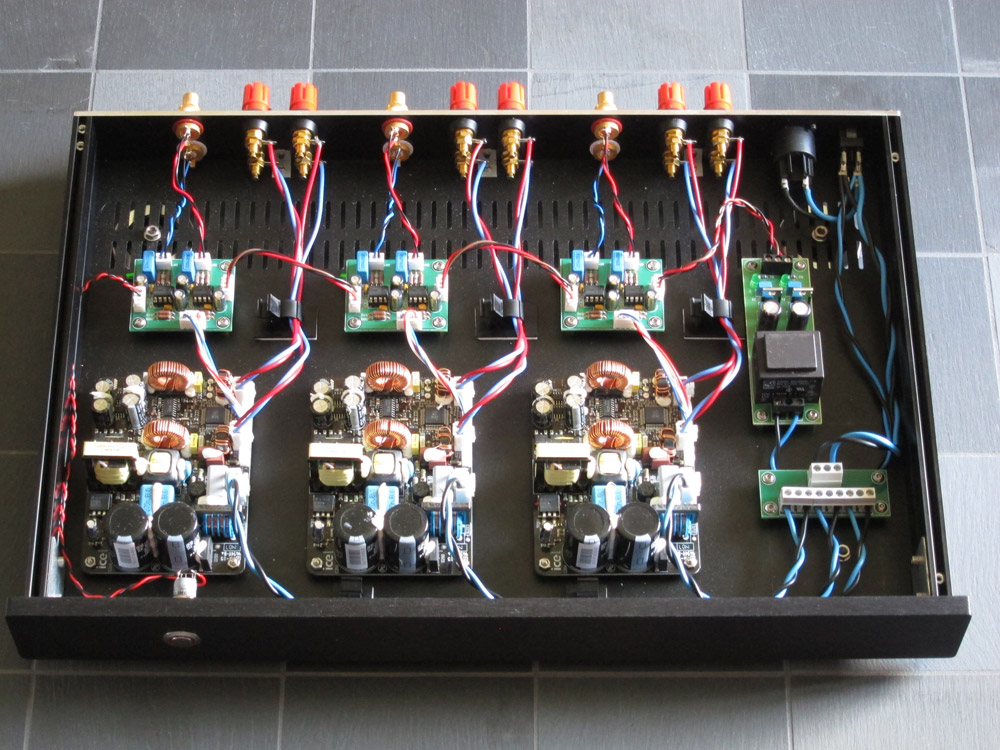
I've just finished building my 7-channel home theatre power amplifier. I used seven LJM L15D Class-D IRS2092 kit boards which I assembled myself. They're powered by two 500W +/-55V SMPS's, with separate speaker protection modules (also kits) powered from the SMPS +15V line, and with a separately powered 5V IR remote on/off relay circuit, so I can control it from my Harmony Remote along with the rest of my system (plus a manual on/off on the front of the amp)
The Right, Centre and Left/
Hi
Can you provide more information or a link to the SMP that you use to this amp?
//Niclas
completed this some time ago, figured i would share my build
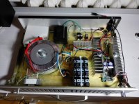
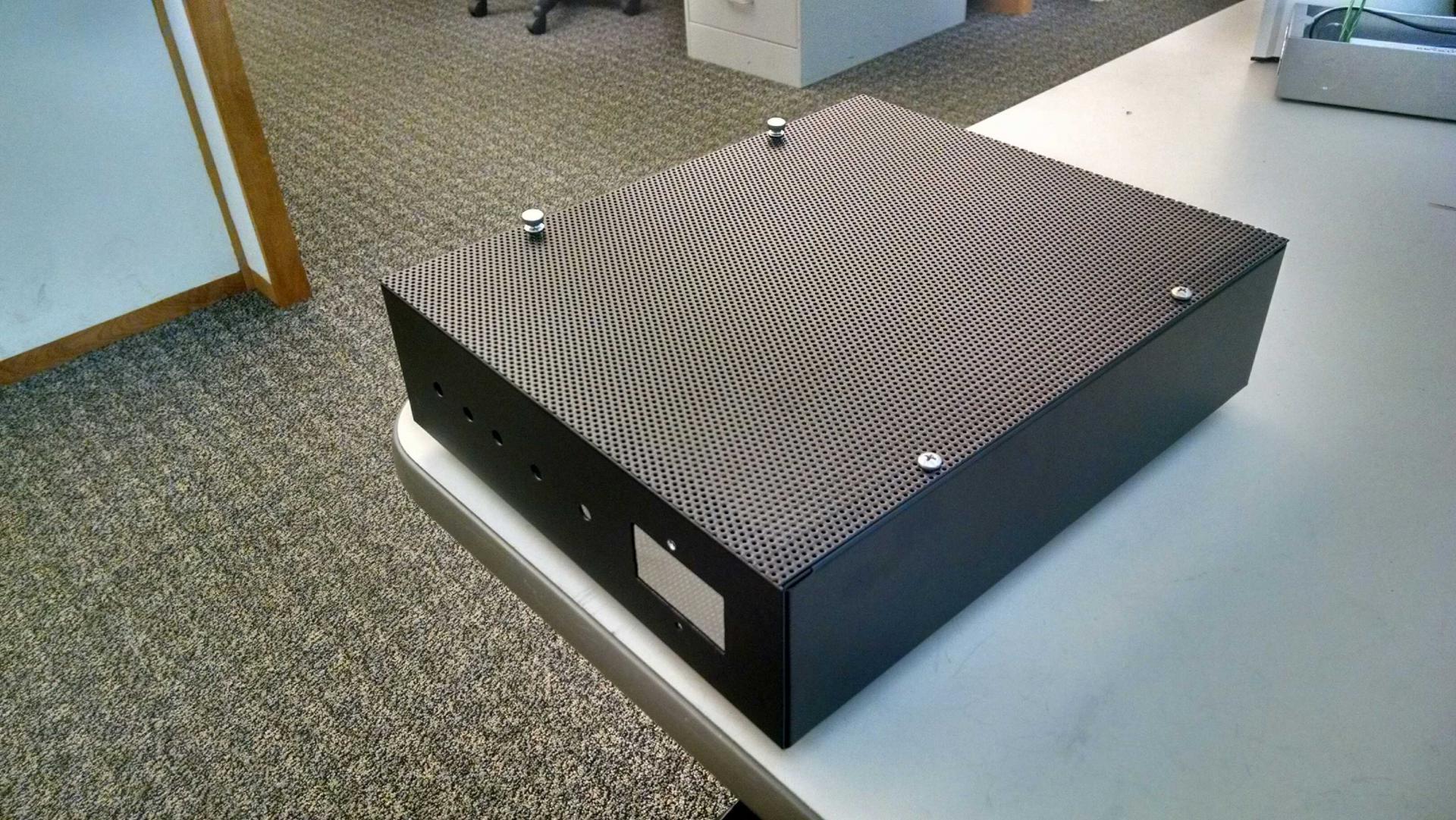
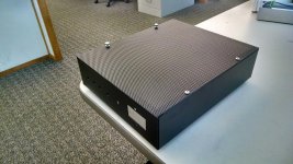
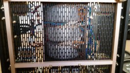
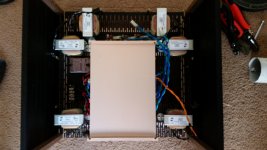
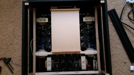
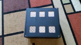
i think i have a 10x8 enclosure, housing 1x icePower 500asp with 2x 500a hangers. enclosure was powder painted and finished with a perforated top.
currently powering 3x diysoundgroup magnum 12s crossed at 200hz. hit hard

i think i have a 10x8 enclosure, housing 1x icePower 500asp with 2x 500a hangers. enclosure was powder painted and finished with a perforated top.
currently powering 3x diysoundgroup magnum 12s crossed at 200hz. hit hard
Attachments

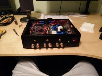
Why did you mount the 500A modules upside down?
since this is all passive cooling, its the only way to get the heatsink to touch and dissipate to the enclosure without making custom angle brackets
Invisible amplifier 
Small project for my home office. A TDA7492 PCB from Ebay and an old electronic Enclosure. I printed a holder for the PCB, Rectifier and Capacitors. A small circuit for the VU Meter with an OP Amp i also fit in the Enclosure. I Use also the Knobs from the original - so ON/OFF, Volume work with the same design before.
Invisible between the other measuring devices 🙂
An externally hosted image should be here but it was not working when we last tested it.
An externally hosted image should be here but it was not working when we last tested it.
An externally hosted image should be here but it was not working when we last tested it.
An externally hosted image should be here but it was not working when we last tested it.
An externally hosted image should be here but it was not working when we last tested it.
An externally hosted image should be here but it was not working when we last tested it.
An externally hosted image should be here but it was not working when we last tested it.
An externally hosted image should be here but it was not working when we last tested it.
An externally hosted image should be here but it was not working when we last tested it.
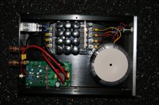
Older project: My ICEpower 50ASX based 6-channel amp with LME49710 input buffers
More pics and writeup in the blog 😀
/U.
Are buffers required? I am putting together a 16 channel IcePower amp using the 50w, and 125w modules. My gain adjustments will be done with a MiniDSP 2x4 for 3 channels which are bi-amped, and the rest of the levels would be controlled via my Yamaha CX-A5100 preamp.
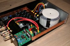
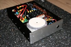
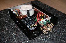
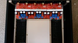
After my first attempt at a stereo amp, here is a second one.
This time a monobloc, based on LJM's implementation of IRAUDAMP9 (1200W 2R design, 1% THD).
A very typical setup. I just removed the heatsinks and replaced them with bare coper bars.
Threaded, and screwed to the sides of the case for better heat dissipation.
The VEE going out of the rectifier board crosses the AC cables, it's awful but I didn't quite anticipate that.
There's a dual output, to connect two 4R subs in parallel.
Attachments
Last edited:
After my first attempt at a stereo amp, here is a second one.
This time a monobloc, based on LJM's implementation of IRAUDAMP9 (1200W 2R design, 1% THD).
A very typical setup. I just removed the heatsinks and replaced them with bare coper bars.
Threaded, and screwed to the sides of the case for better heat dissipation.
The VEE going out of the rectifier board crosses the AC cables, it's awful but I didn't quite anticipate that.
There's a dual output, to connect two 4R subs in parallel.
LJM works ?
I ordered 4, only 1 of them was working . 🙁 and got no refund from ebay 🙁
This copper may seem not thick enough hmm ?
did you increase switching frequency on ljm ?
LJM works ?
I ordered 4, only 1 of them was working . 🙁 and got no refund from ebay 🙁
This copper may seem not thick enough hmm ?
did you increase switching frequency on ljm ?
Yes L30D board. No issue with it yet. I also used two L20D without issue except having to adjust the OCP and the gate resistors. I didn't change the switching frequency. Because I had to mess around with OCP for quite some time to get good results, the ebay seller sent me a third L20D board for free. You could as for that.
The coper is fairly cold actually, even just behind the mosfets, probably because the heat dissipation is efficient.
Surprisingly, it's the output inductor that heats up the most, so I added a coper thingy to link the inductor to the top aluminium cover. It work very well (the top cover now heats up) and keep the inductor at acceptable temperature.
Hi Grizlek
How did you test the modules? What happened? Did you try to get help from the forum here? Maybe open a new thread for that, if not already done.
My experience with class d is there ar a great number of things which can go wrong, and some of thse does not mean thet the amp is burned and will not be able come to work.
/Baldin
Hi Grizlek
How did you test the modules? What happened? Did you try to get help from the forum here? Maybe open a new thread for that, if not already done.
My experience with class d is there ar a great number of things which can go wrong, and some of thse does not mean thet the amp is burned and will not be able come to work.
/Baldin
One was just dead. I changed IRS ic and was still dead, I changed most of elements and it just DO NOT oscillate, maybe error on pcb, I spend more time debugging this one then it cakes to create new one 😀
Once came pressed, cooler and transistors bend, one capacitor broken, BUT box outside was fine, it was "damaged BEFORE packaging. I changed broken cap, and bend transistors with cooler, added 10 ohm between IRS2092 and totem pole driver, (to reduce irs dissipation) increased frequency to 400 khz (NOW core is colder !!!!! does not heat at all), and this one is the only one it WORKS !!! I also added ceramics to totem pole because elcos were burning hot at 400 khz.
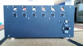
6 Channel Class D Amp
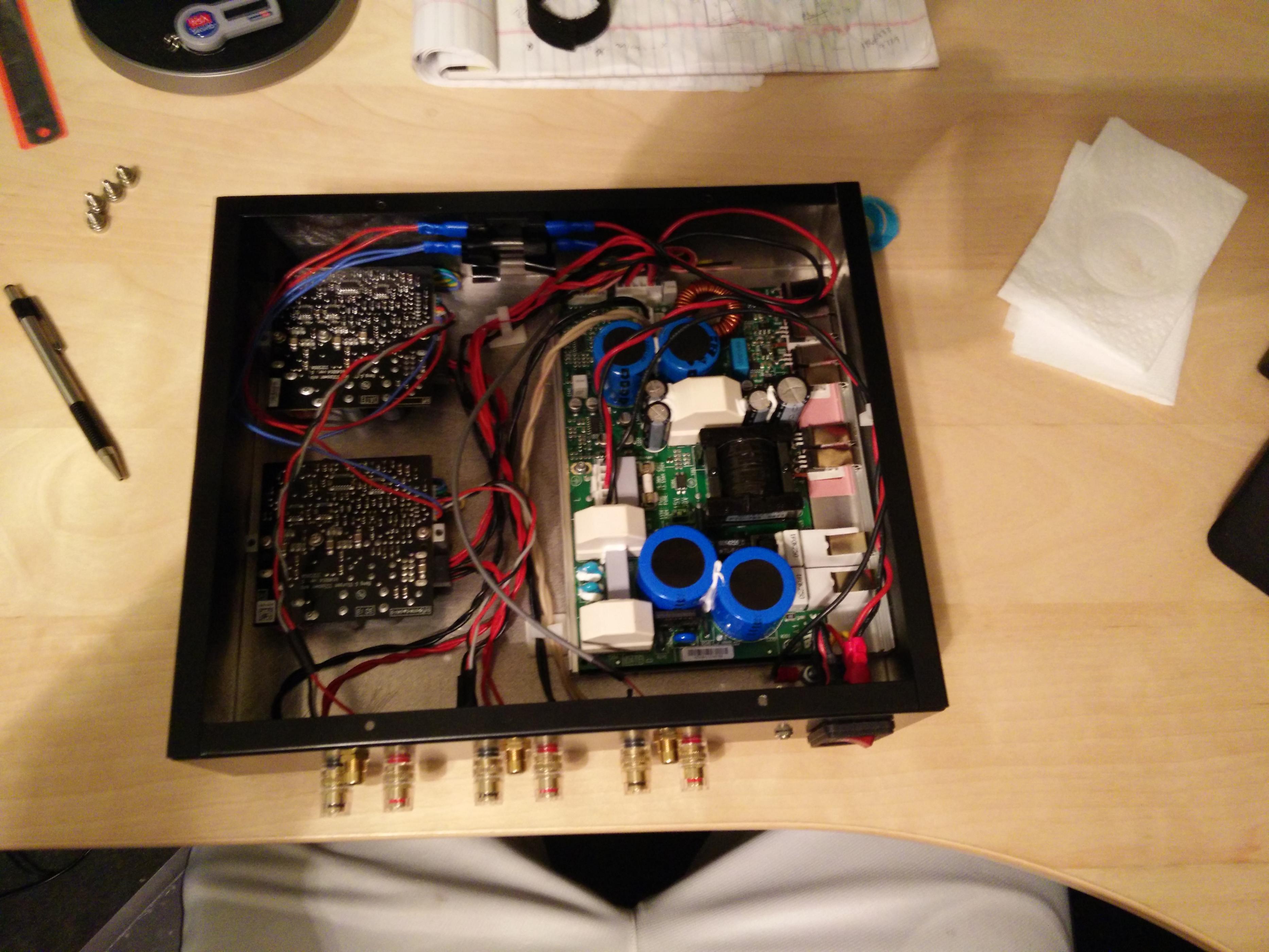
Hello, here is my six channel amp based on three ClassDAudio CDA-258 modules.
Hello, here is my six channel amp based on three ClassDAudio CDA-258 modules.
Attachments

Hello, here is my six channel amp based on three ClassDAudio CDA-258 modules.
Thats a great looking amp!
Can you tell us a bit more about the Display on the front? I got really interested and kinda want that on my upcoming build=)
Do you have any build log for the whole amp project?
- Home
- Amplifiers
- Class D
- Class D Amp Photo Gallery