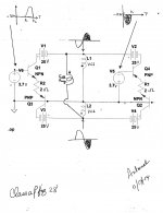
Loudspeaker load to amp
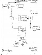
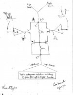
The left image shows the block diagram of the current source aP amp for review. We are at the loudspeaker Zl which splices the sequential positive and negative analog pulses so as to reconstruct an amplified replica of the parent sinewave signal input to the front end of the Precision Rectifier. I have an unusual method to listen to music. I lay on the floor on a firm mattress [ergonomic], and have 2 [R and L ch] loudspeakers which are bolted to the ceiling aim their output at my ears.
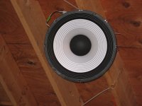
The middle photo shows the left loudspeaker; a 15 inch musical instrument [50 Hz.- 10KHz; 8 Ohms] by MCM. I shot this photo laying on mattress, and zoomed at it.
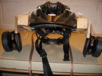
The left photo shows a diy "helmet loudspeaker" for assessment of music quality at very low power output levels [0.3 Vp-p]. Each raw driver is a 4 inch Aluminum cone woofer [65 Hz. - 17 KHz; 8 Ohms.] by MCM. Should one wish to see a selfie of me wearing it; please go to the Headphone Systems Forum ; find the Thread "Does anyone make their own headphones" on page 3 Post #24 dated 25th June or July 2012.
Both loudspeaker systems sound great by either mode of operating the power output stage; meaning enhanced or diminished output current flowing through it. But the enhanced mode of operating the output stage [heads towards saturation] sounds better than the diminished mode [heads towards cutoff].
I'll show several methods to connect the loudspeaker systems, and headphones too.
Best regards.
The left image shows the block diagram of the current source aP amp for review. We are at the loudspeaker Zl which splices the sequential positive and negative analog pulses so as to reconstruct an amplified replica of the parent sinewave signal input to the front end of the Precision Rectifier. I have an unusual method to listen to music. I lay on the floor on a firm mattress [ergonomic], and have 2 [R and L ch] loudspeakers which are bolted to the ceiling aim their output at my ears.
The middle photo shows the left loudspeaker; a 15 inch musical instrument [50 Hz.- 10KHz; 8 Ohms] by MCM. I shot this photo laying on mattress, and zoomed at it.
The left photo shows a diy "helmet loudspeaker" for assessment of music quality at very low power output levels [0.3 Vp-p]. Each raw driver is a 4 inch Aluminum cone woofer [65 Hz. - 17 KHz; 8 Ohms.] by MCM. Should one wish to see a selfie of me wearing it; please go to the Headphone Systems Forum ; find the Thread "Does anyone make their own headphones" on page 3 Post #24 dated 25th June or July 2012.
Both loudspeaker systems sound great by either mode of operating the power output stage; meaning enhanced or diminished output current flowing through it. But the enhanced mode of operating the output stage [heads towards saturation] sounds better than the diminished mode [heads towards cutoff].
I'll show several methods to connect the loudspeaker systems, and headphones too.
Best regards.
Attachments
Just when thought I'd seen it all ! Lols
Antoine's - cool experiments- just suggest spending 2 brave hours in front of a simulator - sims will make it much easier for people to follow.
I started from zero and got to making usable sims in a couple of hours. Just load up the amplifier example in the ltspice install and you're off! Good luck
Antoine's - cool experiments- just suggest spending 2 brave hours in front of a simulator - sims will make it much easier for people to follow.
I started from zero and got to making usable sims in a couple of hours. Just load up the amplifier example in the ltspice install and you're off! Good luck
Just when thought I'd seen it all ! Lols
Antoine's - cool experiments- just suggest spending 2 brave hours in front of a simulator - sims will make it much easier for people to follow.
I started from zero and got to making usable sims in a couple of hours. Just load up the amplifier example in the ltspice install and you're off! Good luck
Hello kasey197. I am glad to hear from you. Thanks for your comments, and suggestion to use ltspice. Does ltspice accept/process analog pulses? Will check it out, and share its outcome if successful. This thread is winding down as I wrote plenty detailed information relevant to both voltage source and current source aP amplification. I hope DIYers got the gist of this approach.
Best regards
Options to connect loads to outputs
I used LTSpice IV which was a free download. Though focused on the development of PSUs, it did a great job nailing down the DC operating conditions on/in the schematics I showed in the past ; e.g. those using Op Amps, and those shown below. The left image is an artwork collaboration between LTSpice IV and I
1. The center points between the dual PSUs [V1, V2] and [V3, V4} are the power outputs which are out of phase.
2. L1 and L2 symbolize loudspeakers; identical or different full range types. Note the phase symbols on them. The loudspeakers can be part of a multi-way system.
3. L1 or L2 may be a dead short to ground. This allows operation via a common collector or a common base configurations.
4. L1 and L2 maybe the primary windings [115 Vac ea.] of a power toroid transformer. Its secondary windings [step down to 12 Vac] feed headphones. I used a 20 Ohm power resistor across each primary winding so as to manage the output level to the headphones.
5. L1 and L2 maybe the secondary windings of the same power toroid transformer so as to step up the power output voltage.
The right image adds more options to use the power outputs.
1. VC1 and VC2 are the two coils of a dual voil coil subwoofer.
2. A full range loudspeaker [e.g. MCM 15" or helmet loudspeakers] connects across the 2 power output ports.
3. All of the drivers maybe part of a multiway loudspeaker system
4. The indicated relative phase of the drivers gave an enhancement in bass performance. I also thought about the role of of back emf [from all drivers] and its effects in this arrangement; since the power outputs may not offer adequate damping.
Best regards
Attachments
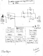
The attached image describes the simplified schematic of one channel of the stereo current source Class aP amp system which I currently listened to. Relevant are VC1 and VC2 which pertain to the 12" infinity brand subwoofer that I had described in post #51. I have two such enclosed subwoofers; whereby each sits in a corner. The full range driver in the schematic is the 15" MCM musical instrument. Thus, I have the equivalent of a 20" full range driver per channel; granted it is bit lean in the high end which may be remedied if desired; most probably by adding a piezo driver.
This system sounds great. The bass is there, the vocals are highly intelligible, and the higher end cymbals too. This reality suggests that this approach to amplification is straight forward, and works damn well. Flip side, had I pushed this as a theoretical approach through LTSpice or equivalent [an a priori E-design] and asked it, and those of you who dabble in it "what do you think? Will it work? Moot point for me; because I [and you too] now have the bulk of its data. My gut feel is that one may need to teach [via programming] the simulation models how to do it; which is beyond my intellectual capability.
I'll give in the upcoming post more objective details which strengthen the validity of this approach to audio amplification.
Attachments

Nagging questions answered.
This style of amplification sends the resultant sequential analog pulse signals [from the Precision Rectifier] along 2 independent; but hopefully identical gain stages prior to reconstructing the parent sinusoid across the load. Are the gain stages matched, and is there a remedy for gain mismatch?
The image shows the approach used to answer both questions. It is a simplified schematic of the amp circuit after the Precision Rectifier.
1. Note the symmetry and my label of Left and Right branches which in a perfect world have identical gain and/or transconductance.
2. I offered the input of the inverting summing [Op Amp] on either side of the output stage, pulse signals which are identical in absolute voltage amplitude, are out of phase and are simultaneous along the time axis. The pulses turn on simultaneously or turn towards cut off simultaneously the output stage. As shown, the polarity of the simultaneous pulses turn off the output stage branches simultaneously.
3. If the gain of the 2 branches is identical, then Vo or Vo' equals zero across the load resistors [8 Ohm] ; because the counter flow of the output currents are identical.
4. Absent a match in the gain of the branches gives a pulse output pointing [up or down on scope] to the branch which is lean or rich relative to the other. Pictorially, it is a matter of algebraic addition of the voltage amplitudes.
5. The magnitude of the pulse [Volts] divided by the load resistor [8 ohm] gives a value of current which is the "extra" from that stage.
6. As a optional remedy to this mismatch in transconductance, one may then lower the gain of the culprit preceding [inverting summing] stage to null the gain mismatch. Or one may increase the gain of the stage which is lean in transconductance [Right or Left branch] to reduce the amplitude of the pulse [on scope] down to zero.
7. But note that I have the tool to "distort" at will the reconstructed sinusoid, and listen to the outcome of my deliberate tampering with it [the parent music] by using the helmet or the larger loudspeakers I described. Why? Because I can do it, and I am curious to link between cause and effect.
More detail coming up with pics on the performance of the actual amp under study.
Attachments

The following adds detail to the above post. The left image is the test circuit used to measure the relative gain of the analog pulses [first], and then optionally to increase or decrease it.
A 1 KHz. positive going pulse from the Precision Rectifier was buffered by OA1. Its resultant positive going output pulse was simultaneously fed to a classical Op Amp inverter. I matched the values of the 3.9 K input and feedback resistors [of inverter] to ~2 parts per 700 parts by using a digital multimeter on the AC scale which gave me readings [just numbers] to show the relative extent of match. The data of [v+ and v-] which are shown on the lower left side of the left image are the example matching values of the pulses at the Initial or State 1 conditions of the experiments.
The simultaneous positive going and independent negative going pulses were presented to the inputs of the current source aP amp as shown in the right image which was a diagram shown in the above post. The objective was to determine the relative gain of the independent amplifying branches [Left and Right], and then define an extent of mismatch or asymmetry between them. Then to optionally null this asymmetry, or increase it by favoring one branch over the other.
Here was the experiment as one looks at the right image.
1. Apply a positive pulse only to the input of Left branch. Ground the input of the Right branch.
2. Adjust on the scope the resultant positive going pulse to 8 Volts peak [meaning 1 A peak in 8 Ohm power resistor]. The resultant scope photo is the one on the left.
3. Introduce the simultaneous negative going pulse to the input of the Right branch. The resultant was a net positive going pulse of ~0.2 Vp as seen on on the right scope picture of the first row of attachments. This result said that the inherent gain of the Left branch was slightly higher than that of the Right branch, and the calculated asymmetry was ~25 milliamps [~0.2 Vp divided by 8 Ohms load resistor]. Relative to 1 Amp, the calculated asymmetry in gain was 3%.
4. The test circuit was on Proto Board, and resistor R1 [150 K by trial and error] was added in parallel with the input resistor [3.9 K] of Op Amp inverter so as to raise the net gain of the Right branch [by ~3 %] relative to that of the Left branch.
5.The tabulated results in the bottom middle of the left image [State 2; Adjust}show that I was able to null the inherent asymmetry or gain inequality; believing that it is real. The lone scope photo in the second row of attachments shows this null. The vertical scale was 20 mV per division. I equate this "nulling" action to a deliberate manual overall loop negative feedback.
6. The tabulated results in the bottom right view of the left image, show that I aggravated the Initial asymmetry in the gain [State 1] by further decreasing the gain of the Right branch [R2//3.9 K] relative to that of the Left branch which [Left branch] was higher to begin with. The resultant scope output is the most bottom view, and the calculated new gain mismatch or asymmetry was increased to 5%.
Next steps will be to hear music infused with these deliberate asymmetries. I'll report the hearings.
Best regards
.
Attachments

Please note:
1. The placement of the scope photos in the final display of the previous post has changed from my description.
2. The polarity of the pulses which were offered to the inputs of the amp in the previous post "moved the conduction of the bjts in the output Left and Right branches" toward simultaneous cut off.
3. Clearly, by reversing the polarity of both pulses at the inputs of the amp compared to the above case, the conduction of the bjts in the left and right branches will be increased. I'll do this simple experiment for completeness by reversing the RCA plugs at the amp's inputs, and collecting data like done the in previous post. No change in the objective of the experiments.
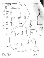
Maybe a useful tool to match devices' performance
The image shows schematics I scribbled of three output stage configurations which are commonly used. The objective is like that stated above which is to determine the relative gain of the 2 devices, and then find a solution to bring their gain closer to a match if desired. The tools to enable this are the same as I used in the previous post.
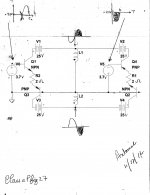
The top left part of the image suggests the use of equal [absolute] amplitude, out of phase, simultaneous and independent input signals Vi and Vi' which have the corresponding shapes of the following options a, b, and c. For example:
1. Option [a] inputs 2 independent sinewaves of equal amplitude [mind it!] which are 180 degrees out of phase to its respective device.
2. Pulse options b and c simultaneously turn on and turn off the 2 devices respectively.
3. The variable batteries at the gates of the devices generate their forward bias.
The image shows schematics I scribbled of three output stage configurations which are commonly used. The objective is like that stated above which is to determine the relative gain of the 2 devices, and then find a solution to bring their gain closer to a match if desired. The tools to enable this are the same as I used in the previous post.
The top left part of the image suggests the use of equal [absolute] amplitude, out of phase, simultaneous and independent input signals Vi and Vi' which have the corresponding shapes of the following options a, b, and c. For example:
1. Option [a] inputs 2 independent sinewaves of equal amplitude [mind it!] which are 180 degrees out of phase to its respective device.
2. Pulse options b and c simultaneously turn on and turn off the 2 devices respectively.
3. The variable batteries at the gates of the devices generate their forward bias.
Attachments
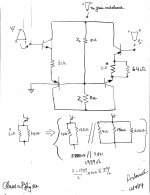
An approach to idealized complementary symmetry
The top part of the attached image shows a simplified drawing of the output stage for the current-source analog pulse amplifier. The load resistors [Zl = 8 Ohm] are a pseudo fence which separate the bjts of the left branch from the complementary bjts of the right branch. The objective was to render the gain of the left branch equal in magnitude to that of the right branch as follows:
1.Apply a positive-going 1 KHz pulse [duration 0 to t seconds] to the input of the left branch only so as to derive 1 Amp across either load resistor.
2. Apply next to the input of the right branch the simultaneous negative going 1 KHz pulse [duration 0 to t seconds], and of absolute equal amplitude to that of the positive-going pulse.
3. The scope showed a negative going pulse at the top Vo output port which meant a slight gain imbalance between the two bjt branches due to a higher gain of the left branch relative to that of the right branch. The magnitude of the current imbalance was a meager 30 mA peak or ~3% based on 1 Amp derived in step 1.
4. The equivalent inter emitter resistor R =2*Ohm of the right branch was next reduced to 1.939 Ohms [calculated for show; ignore significant figures rules] by paralleling with it the equivalent value of 64 Ohms. This increased the gain of the right branch by ~3 % which diminished the net gain imbalance to ~0.5% [or ~50 mV peak offset across 8 Ohms or ~6 mA peak current imbalance in the loads].
5. I show underneath the schematic the actual values of the resistors used to balance or tweak the output stage of the Right music channel.
6. The Left music channel also showed a gain imbalance of ~2%; because the gain of the left branch was lower than the right branch. It was corrected [diminished to ~0%] as done above with 150 Ohms in parallel with one of the 4 Ohm inter emitter power resistors of the right branch.
Subjective evaluations coming up.
Best regards.
Attachments
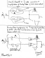
Compare the performance of Class AB with that of Analog Pulse
Its time for the rubber to meet the road. Early on in this thread, Jan Didden noted that Class B and it improved variant Class AB process analog pulses; which is well established [long history] and is further evidenced by the plethora of respectable commercial power amps, and their technologies. The attached image uses two simple graphics to compare/contrast the operation of this formal Class AB with that of Analog Pulse under study.
The top graphic [highly simplified] portrays the operation of a Class AB power output stage.
1. Each power output bjt simultaneously; aka in situ generates via rectification analog pulses and amplifies them during their allocated times.
2. Rectification means that the positive going [shaded] component of the input sine wave signal is separated from its negative [clear] component.
3. The time [t] at the zero crossing of the input sine wave signal is the "tether" point whereby the positive going pulse joins with that of the negative pulse. This electrical joint is severed to give analog pulses which are sequentially processed by NPN and PNP.
4. The load Zl re-joins the pulses at the tether point [time = t] and thus reconstitutes an amplified replica of the input sine wave.
The bottom graphic portrays the operation of Analog Pulse amplification under study.
1. Analog pulses are generated in a precision rectifier [Op Amp circuit] which is independent of, or totally unrelated to the power output bjts. Furthermore, the resultant analog pulses are totally independent of each other. They are no longer tethered or electrically joined at time [t].
2. The resultant analog pulses are the same as, and/or very much like those generated in situ in the above Class AB output stage.
3. The identical bjts in the Class AB output stage [top graphic] have the sole role to amplify sequentially the pulses which are them tethered at time [t] to reconstitute a replica of the input sine wave signal.
Class AB and Analog Pulse amplification share a "common processing" of analog pulses. They differ as shown above by the method used to generate the analog pulses; in situ for Class AB versus independent for Analog Pulse amplification.
This question bothers me. Why bother with Analog Pulse amplification which adds complexity vis a vis that of Class AB which is simpler and already does a great job?. The tentative answer is potential flexibility in operation, control over the analog pulses.
Coming up are objective and subjective comparisons between Class AB and Analog Pulse amplification.
Attachments
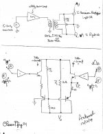
Compare operation of Class AB with Analog Pulse Amplification
Class AB was compared side by side with Analog Pulse Amplification [APA]. I have a dual channel current source APA which was readily configured to also operate Class AB. So the Right music channel was operated APA and the Left music channel was simultaneously operated Class AB. The reverse connectivity worked as well and gave similar performance.
The image shows the details of this experiment. Its top part was the set up which generated two simultaneous low impedance, out of phase, and equal amplitude sine wave signals. The sine wave [F=130 Hz] from the signal generator was fed to a utility power amp [SONY] which drove the primary winding of a power transformer. One resultant stepped down signal fed the Precision Rectifier of the Right Channel APA, while its out of phase companion bypassed the Precision Rectifier of the Left channel, and fed the amplifier directly. The reason the input signals were out of phase was to correct for the phase inverting property of the Precision Rectifier. The side by side amplification set up is shown in the bottom part of the image, and is simplified.
1. Input ports A and B belong to the Right channel and receive analog pulses from the Precision Rectifier which are sequential in time. Note their polarity, and application time to their respective input ports.
2. Input ports A' and B' belong to the Left channel. They receive simultaneous sine wave signals from the secondary winding of the power transformer.
3. Each of the left and right branches of the output stage [for each music channel] were forward biased to idle at a net ~60 mA.
4. The main load resistors are 2 Ohms for each music channel.
5. Scope photos were then taken at the Test Point [T.P.] which is at one of the two inter-emitter 4 Ohm resistors of the right branch.
The system was operated for ~1 hour before scope photos were taken. The photos will be shown in comparative pairs at 3 different operating conditions. I will show one pair per post.
Best regards
Attachments

The first order of business was to raise the voltage gain of the Analog Pulse Amplifier [APA] to match that of the Class AB amplifier. This was done by lowering the value of the input resistor [1.5K] to the Precision Rectifier [see schematic in post #72] by paralleling it with 1.8K [trial and error]. The resultant voltage gain of Class AB was Vo/Vi = 0.150Vpp/0.26 Vpp = 0.58 versus that of APA =0.16Vpp/0.26Vpp = 0.62. Noting that Vo is the output voltage in the image at the joint opposed collectors of the common base configured bottom bjts.
The power resistors [25 Ohm] across the load resistor Zl = 2 Ohm were prescribed by loudthud in post #35 so as to dampen reactive loudspeaker loads. They are a permanent fixture of the output stage, and their center point was grounded so as to reference voltage output measurements to common.
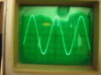
1. The left scope image belongs to the Class AB amplifier [Left music channel] measured at the Test Point [T.P.] which is shown in the image. It is a sinewave which has a peak to peak amplitude of 4.2 div X 50 mV/div = 0.21 Vpp. This state implied the Class AB amp operated in Class A. Its shape [looks] were the same down to lower millivolt levels.
2. The right scope image belongs to APA [Right comparative music channel] also measured at its T.P. It is the expected analog pulse which had a peak absolute amplitude of 4 div X 50 mV/div = 0.2 Vp. Its shape [looks] were the same down to 5-10 mVp at the same T.P.
3. The scope photos describe the comparative difference in operation between Class AB [in its low signal level Class A state] and that of APA.
4. It follows that Class AB in this Class A state of operation is expected to perform better than APA in a subjective music comparison. It did, and I'll tell you about it in the next post.
5. But, the way forward in later posts to further improve APA relative to Class AB in its current Class A operation will be to operate the Precision Rectifier in a less precise manner; meaning operate the Precision Rectifier in Class AB versus its current state of Class B [absent crossover distortion]. Forthcoming.
Best regards.
The power resistors [25 Ohm] across the load resistor Zl = 2 Ohm were prescribed by loudthud in post #35 so as to dampen reactive loudspeaker loads. They are a permanent fixture of the output stage, and their center point was grounded so as to reference voltage output measurements to common.
1. The left scope image belongs to the Class AB amplifier [Left music channel] measured at the Test Point [T.P.] which is shown in the image. It is a sinewave which has a peak to peak amplitude of 4.2 div X 50 mV/div = 0.21 Vpp. This state implied the Class AB amp operated in Class A. Its shape [looks] were the same down to lower millivolt levels.
2. The right scope image belongs to APA [Right comparative music channel] also measured at its T.P. It is the expected analog pulse which had a peak absolute amplitude of 4 div X 50 mV/div = 0.2 Vp. Its shape [looks] were the same down to 5-10 mVp at the same T.P.
3. The scope photos describe the comparative difference in operation between Class AB [in its low signal level Class A state] and that of APA.
4. It follows that Class AB in this Class A state of operation is expected to perform better than APA in a subjective music comparison. It did, and I'll tell you about it in the next post.
5. But, the way forward in later posts to further improve APA relative to Class AB in its current Class A operation will be to operate the Precision Rectifier in a less precise manner; meaning operate the Precision Rectifier in Class AB versus its current state of Class B [absent crossover distortion]. Forthcoming.
Best regards.
Attachments
Compare operation and subjective performance of Class AB with APA
A comparison of the subjective performance of Class AB with Ananolg Pulse Amplification [APA] was done as follows.
1. The drivers of the "helmet headphone" were connected in parallel for a mono application.
2. The Right headphone output of a SONY CD player [remote vol. control] was split in two with a Y RCA connector. One signal went to the Precision Rectifier, and the other to the input of Class AB.
3. Note that the power output signals are out of phase; because the Precision Rectifier inverts overall phase referenced to the output headphone signal of CDP.
4. The helmet headphone was connected to Class AB output as shown above instead of its Zl = 2 Ohm. The APA was loaded with Z l= 2 Ohm during the assessment.
5. I listened to a cut of music [Dave Grussin] containing low level/soft instrumental information.
6. Music was then stopped, and the helmet headphone was connected to the output of APA [less the original Zl =2 Ohms]. The leads of the headphones were reversed across the outputs of APA to correct for overall absolute phase. The power outputs of Class AB amp were loaded with Zl = 2 Ohms. I gave myself 1 minute or less to do this.
7. The same cut of music cut was replayed. This approach of subjective assessment was repeated with other low level music containing vocals. I had/have no doubt that Class AB in its operational state of Class A sounded more pleasing than that of APA.
8. This subjective assessment was commensurate with the objective performance in the scope photos of the previous post. I reconciled between objective with subjective performance.
Next, a pair of scope photos comparing Class AB operating in its Class B domain versus APA.[higher power outputs than this current case.
Best regards.
Compare operation of Class AB with APA
The previous post noted that I liked the subjective performance of Class AB [in its Class A state] better than that of APA. By this I did not mean that the subjective performance of APA was poor. On the contrary, the comparative sound due to APA was fully satisfactory, detailed and also pleasing in its Class B operation; absent crossover distortion [aka precision rectification] and its no-turn-off idle state of all of its power bjts.
Their is nothing special about the T.P. used. Its complementary T.P. gives positive going pulses [for APA], and there's is more information that is present at the emitters of the CB configured bottom bjts for added operational comparison.
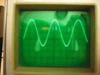
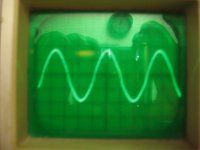
1. The left scope photo belongs to the Class AB amp. Its amplitude is 3.6 div X 0.2 V/div = 0.72 Vpp.; more power output relative to the first case. Note the rounding of the "hills", which implied shaving off amplitude from the positive going component of the sine wave; aka operating within its Class B domain.
2. The right scope photo belongs to APA. Its absolute amplitude is 4 div X 0.2 V/div = 0.8 Vp. Its looks are like that shown above in the previous post. Note here, that the signal in Class AB at T.P. lost amplitude compared with the pulses in APA at T.P.; despite offering equal amplitude input signals to both amps.
3. Both scope photos characterize operation of Class AB versus APA at specified conditions. They [scope photos = operation] do not look alike.
As a continuation to the subjective evaluation of Class AB [now partly operating in the Class B domain] versus APA, I liked the performance [via the helmet headphones] of APA better than that of Class AB for the louder music passages. Class AB came across as lazy, and had a weak punch. By contrast, APA was agile, had fast-like performance, and was relatively louder than that due to Class AB.
More scope photos forthcoming at still higher power output levels.
The previous post noted that I liked the subjective performance of Class AB [in its Class A state] better than that of APA. By this I did not mean that the subjective performance of APA was poor. On the contrary, the comparative sound due to APA was fully satisfactory, detailed and also pleasing in its Class B operation; absent crossover distortion [aka precision rectification] and its no-turn-off idle state of all of its power bjts.
Their is nothing special about the T.P. used. Its complementary T.P. gives positive going pulses [for APA], and there's is more information that is present at the emitters of the CB configured bottom bjts for added operational comparison.
1. The left scope photo belongs to the Class AB amp. Its amplitude is 3.6 div X 0.2 V/div = 0.72 Vpp.; more power output relative to the first case. Note the rounding of the "hills", which implied shaving off amplitude from the positive going component of the sine wave; aka operating within its Class B domain.
2. The right scope photo belongs to APA. Its absolute amplitude is 4 div X 0.2 V/div = 0.8 Vp. Its looks are like that shown above in the previous post. Note here, that the signal in Class AB at T.P. lost amplitude compared with the pulses in APA at T.P.; despite offering equal amplitude input signals to both amps.
3. Both scope photos characterize operation of Class AB versus APA at specified conditions. They [scope photos = operation] do not look alike.
As a continuation to the subjective evaluation of Class AB [now partly operating in the Class B domain] versus APA, I liked the performance [via the helmet headphones] of APA better than that of Class AB for the louder music passages. Class AB came across as lazy, and had a weak punch. By contrast, APA was agile, had fast-like performance, and was relatively louder than that due to Class AB.
More scope photos forthcoming at still higher power output levels.
Attachments

The Class AB and AP Amps were pushed further to deliver more output power into Zl = 2 Ohms so as to derive additional operational comparison between them [aka compare and contrast] which may explain additional subjective assessments [not with the helmet headphone due to their current high power outputs].
1. The input signal [Vi] was increased and was identical in magnitude to both amps.
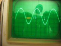
2. The signal at T.P. was next adjusted for APA to be equal 3 div X 0.5 V/div = 1.5 Vp. This is shown in the right scope photo, and its looks are much like the previous others shown earlier.
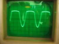
3. The left scope signal at T.P. belongs to Class AB; now operating deeper in its Class B domain. Its amplitude was 2.5 div X 0.5 V/div = 1.25 Vpp. Note the loss in its amplitude relative to that of APA, and the rounding off the "hilly' portions of its "harmonic" signal.
4. I can discern that the signals at T.P. for Class AB are "analog pulses" which to a certain extent look like those shown for APA. I can also say the signal of Class AB is a distorted sine-wave and not analog pulse. By contrast, I am unable to say the signals for APA are sine wave -like!
5. Most important is that the objective and subjective performance of the amps are expected to be different because their in-process signals [scope photos] are not exactly alike.
The next post will show the attendant power output signals at Vo of the bottom CB-configured bjts.
1. The input signal [Vi] was increased and was identical in magnitude to both amps.
2. The signal at T.P. was next adjusted for APA to be equal 3 div X 0.5 V/div = 1.5 Vp. This is shown in the right scope photo, and its looks are much like the previous others shown earlier.
3. The left scope signal at T.P. belongs to Class AB; now operating deeper in its Class B domain. Its amplitude was 2.5 div X 0.5 V/div = 1.25 Vpp. Note the loss in its amplitude relative to that of APA, and the rounding off the "hilly' portions of its "harmonic" signal.
4. I can discern that the signals at T.P. for Class AB are "analog pulses" which to a certain extent look like those shown for APA. I can also say the signal of Class AB is a distorted sine-wave and not analog pulse. By contrast, I am unable to say the signals for APA are sine wave -like!
5. Most important is that the objective and subjective performance of the amps are expected to be different because their in-process signals [scope photos] are not exactly alike.
The next post will show the attendant power output signals at Vo of the bottom CB-configured bjts.
Attachments

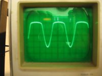
The scope photos portray the resultant power output harmonic signals attendant to the previous post.
1. Vi to both amps [from the secondary of the power transformer] was 3.6 div X 0.5 V/div = 1.8 Vpp. Needed to calculate voltage gain.
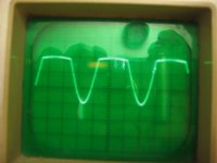
2. The right scope photo pertains to Class AB operating deeper in its Class B domain. The amplitude of its power output signal [at Vo in the schematic of image] was 3.6div X 0.2 V/div = 0.72 Vpp across Zl = 2 Ohm. Voltage gain of Class AB amp = 0.72 Vpp/1.80 Vpp = 0.4 which is a significant drop from its original value/ performance in Class A equal to 0.6. The signal appeared distorted with a discontinuity in its middle part.
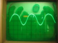
3. Theleft scope photo pertains to APA. The amplitude of its power output signal is 6 div X 0.2V/div = 1.2 Vpp. Its voltage gain was 1.2 Vpp/1.8Vpp = 0.66 which is similar to that observed early on in the experiment at lower power output levels. The signal peaks appeared to me "pointy"; but its overall look was like that of the input signal at 1.8 Vpp.
One may conclude that the side by side comparison of the amps at the 3 different power levels resulted in different in-process performance, with an overall differentiated objective and subjective performance. I am inclined to suggest that APA operates in a unique manner, and venture to say that it operates in a class of its own.
1. Vi to both amps [from the secondary of the power transformer] was 3.6 div X 0.5 V/div = 1.8 Vpp. Needed to calculate voltage gain.
2. The right scope photo pertains to Class AB operating deeper in its Class B domain. The amplitude of its power output signal [at Vo in the schematic of image] was 3.6div X 0.2 V/div = 0.72 Vpp across Zl = 2 Ohm. Voltage gain of Class AB amp = 0.72 Vpp/1.80 Vpp = 0.4 which is a significant drop from its original value/ performance in Class A equal to 0.6. The signal appeared distorted with a discontinuity in its middle part.
3. Theleft scope photo pertains to APA. The amplitude of its power output signal is 6 div X 0.2V/div = 1.2 Vpp. Its voltage gain was 1.2 Vpp/1.8Vpp = 0.66 which is similar to that observed early on in the experiment at lower power output levels. The signal peaks appeared to me "pointy"; but its overall look was like that of the input signal at 1.8 Vpp.
One may conclude that the side by side comparison of the amps at the 3 different power levels resulted in different in-process performance, with an overall differentiated objective and subjective performance. I am inclined to suggest that APA operates in a unique manner, and venture to say that it operates in a class of its own.
Attachments

I have not built anything like the APA, but I have built class AB amps. Many times a clean looking sine wave can have one or more percent distortion. What I find most illuminating is looking at the output of a distortion analyzer, the output with the fundamental nulled. You can quickly see crossover distortion and find a bias setting that minimizes it. Or you can see when the positive and negative sides are out of balance. Even a simple tunable twin T filter reveals much more than a simple Y-T oscilloscope display. I think such techniques will help you fine tune the precision rectifier and output stages.
I have not built anything like the APA, but I have built class AB amps. Many times a clean looking sine wave can have one or more percent distortion. What I find most illuminating is looking at the output of a distortion analyzer, the output with the fundamental nulled. You can quickly see crossover distortion and find a bias setting that minimizes it. Or you can see when the positive and negative sides are out of balance. Even a simple tunable twin T filter reveals much more than a simple Y-T oscilloscope display. I think such techniques will help you fine tune the precision rectifier and output stages.
Thanks Loudthud for your input and recommendations. I've been using my ears and the scope to guide this hobby. More detailed work will be needed to optimize such systems.
Best regards.
Jan Didden noted that Class B and it improved variant Class AB process analog pulses; .
Beg to differ - if you read that in my post I have not been clear. I find that this 'pulse' terminology is completely wrong and gives the impression that all you are interested in is sine waves.
The whole issue is separating signal polarities in the pre-stages and combining them again in the output stage.
Without a scope and/or just ears it's pretty much impossible to do a reasonable job in this endeavor. At least get a $250 Rigol scope or something similar and you will look at your circuit with new eyes!
There is a reason that this tread is mostly a monologue.
Jan
- Home
- Amplifiers
- Pass Labs
- Class aP amplification