Ed:
Nothing to apologize for with your philosophy - it is sound and works for me, also.
I think the major risk/downside for high levels of feedback is verifying that the design is stable enough.
👍
Pushing for the spectacular numbers is often fun, can be educational as well and definitely grants bragging rights.
It is very impressive to see the performance level of designs that can be built by hobbyists at home these days.
🙂
At those levels, attention to minute details of so many other things can have significant impacts. Just to name a few: lead dress & wires routing, grounding, magnetics orientation in the chassis. At some point, the "law of diminishing returns" or "this fanaticism has stopped being fun" sets in. I think if you do a thoughtful job at defining and verifying the specs you value, the distortion spectrum is pleasant and you like the sound of the result, you're good to go.
At this point in my life, for me it is more fun and interesting to try to listen to differences in global feedback amps vs non-global feedback amps than driving for the lowest numbers.
But that being said, I did enjoy reading the book "Audio Power Amplifiers - towards inherently linear amplifiers" by Arto Kolinummi
(https://linearaudio.net/books/2220). I just wish the book had included more actual photos of prototypes, wiring and PCB layouts to support some of the spectacular performance claims made, especially for non-global feedback designs.

Agreed. I know how to do RF design and layout. I don't know as much about the second pole as the first. I am loathe to add an output inductor.I think the major risk/downside for high levels of feedback is verifying that the design is stable enough.
I suspect that my amplifier and the Wolverine would be indistinguishable in an ABX test. Both have low enough distortion not to matter.At this point in my life, for me it is more fun and interesting to try to listen to differences in global feedback amps vs non-global feedback amps than driving for the lowest numbers.
I am not going for no-global-feedback because I feel that "pleasant distortion" is a misconception. There is no pleasant distortion when playing more than one note at a time. I value the instruments remaining distinct (and I can hear every one in good recordings).
What was old is new again. 😉But that being said, I did enjoy reading the book "Audio Power Amplifiers - towards inherently linear amplifiers" by Arto Kolinummi
(https://linearaudio.net/books/2220).
Thanks,
Ed
Thanks @EdGr!lineup - That is consistent with my analysis. The voltage across the emitter resistors should be ~20mV.
Ed
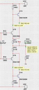
How about this output stage?
It is CFP.
How to think and design for best result?
SPICE shows 54mA bias at 1 Watt for lowest distortion.
Douglas Self has investigated crossover dist in 'Distortion in Power Amplifier'
Attachments
You seem to have strong faith in the accuracy of SPICE models at low currents and switching ON/OFF
I know it is not for real.You seem to have strong faith in the accuracy of SPICE models at low currents and switching ON/OFF
It only can give some hint with SPICE.
I have never said I believe SPICE is more than a bit from actually building.
But it is sure is fun! 🙂
What about bypassing the emitter resistors with capacitors to reduce the local feedback, but retain the positive effect of the resistors on the DC and temperature conditions? Kinda like with the cathode resistor in triode input stages. Could that actually work? There are supercapacitors now, which pack 50 Farads at ~20mOhm ESR, able to withstand 30+ Amps; the voltage rating of 3V should be adequate in this case. Didn't get around to simulate this, but stumbling on this thread just made me remember this idea.
Those resistors do very little to stabilise bias, they are more often for output protection. Just 20mV is inot enough to control thermal run away
20mV? At 50mA bias 0.2 ohms gives 10mV total.Those resistors do very little to stabilise bias, they are more often for output protection. Just 20mV is inot enough to control thermal run away
Still, I agree with your point with a proviso that a well designed bias stabiliser MIGHT be able to control quiescent current. Not the usual one transistor circuit though.
All this assumes a constant bias voltage, which is typical but not a given. Have a look at LVs "Tandem" regenerative driver bias, which cancels the output Vbe (+Re) with a ~diamond driver Vbe. The generative bias means the (diamond) driver current and OP current are in phase instead of inverted. I'm sure there are more ways to mitigate the EF distortion. Perhaps it becomes a moot point as this topology is good enough for most applications and irrelevant for those who want something "better". Thermal stability often pushes the bias down to less-than-optimal THD settings. Very few customers actually care about THD less than 0.01%. Stability, reliability & ruggedness, and clean clipping are more important.
Yes, the point I was making was that the voltage drop across your typical 0.2 Ohm emitter resistors is so small, that it does not contribute much to thermal stability., although that is what is claimed all the time in design articles and text books. They usually exist to trigger current limit circuits when the voltage across them reaches around 0.6V20mV? At 50mA bias 0.2 ohms gives 10mV total.
Still, I agree with your point with a proviso that a well designed bias stabiliser MIGHT be able to control quiescent current. Not the usual one transistor circuit though.
lineup - The CFP requires a more complicated analysis. It has two exponentials and twice as many crossovers.
For the emitter follower, I can safely ignore the driver stage because it runs in class A in my amplifier.
As you can tell, I like the emitter follower.
Preamp - Thanks for mentioning supercapacitors. I have not looked into them in detail. The 1,000-hour life seems problematic.
davidsrsb and john_ellis - I have done extensive analysis of bias stability on my amplifier. The emitter resistors control the range of bias currents. The bias increases a lot with the output transistors' temperature. The resistors hold the upper end to a safe dissipation (which is less than the dissipation at 64% amplitude).
The important thing to realize is that bias current controls idle power without adding to the maximum dissipation.
The thermals have to be designed to handle the maximum dissipation, and the idle power just has to never come near that value.
steveu - I too prefer not blowing up. 😉
Ed
In Distortion in Power Amplifier Douglas Self found that CFP had lower crossover distortion.
http://www.douglas-self.com/ampins/dipa/dipa.htm#2
http://www.douglas-self.com/ampins/dipa/dipa.htm#2
lineup - Interesting. The distortion caused by the emitter-follower driver stage can be reduced by applying more bias and using higher Hfe output transistors.
Ed
Ed
Thanks for mentioning supercapacitors. I have not looked into them in detail. The 1,000-hour life seems problematic.
From what I've found so far, end-of-life is loosely defined as 70% of initial capacity and 200% of initial ESR. Don't know how those values deteriorate after that, but in this case I wouldn't consider that problematic.
Unfortunately there's another thing which actually is problematic. The currents through the emitter resistors are highly asymmetric and don't roughly cancel out, like the whole signal usually does. Thus there's a substantial charge buildup in those capacitors, which then act like batteries and push the output transistors deep into cutoff. Bummer. Temperature compensation looks like a breeze, once you increase those emitter resistors to 10 Ohms each.
In a class AB stage, the resistor voltage is not constant. You may set it to 0.025V at idle, but a 3 Amp peak in 0.22 Ohms is 0.660V. The emitter will charge-up the cap very quickly. After that the transistor is BACK-biased about 0.635V, or nearly-off, until the charge on the cap leaks off.What about bypassing the emitter resistors with capacitors to reduce the local feedback, but retain the positive effect of the resistors on the DC and temperature conditions?
Also: what value cap do you propose? To "bypass" 0.22r down to 50Hz is 15,000ufd; nearly 40,000uFd or 40mFd for 20Hz (because crossover in a subwoofer may be extra offensive buzz).
This blind alley is nearly 70 years old. Emitter/source/cathode caps for speech/music MUST work class A.
I know of 3 and a half alternatives to typical AB biasing. In general, these methods are independent of the OP temperature because the Vbe is not involved:
1. Autobias such as that used by LV in his posts. The bias senses the base current and reduces it, except when overdriven by the VAS. IE there is a minimum Vbe set by diodes etc.
2. Run the OP's with a tiny idle current and let the faster drivers do the "switching". This requires cross coupling.
3. The "Tandem" circuit drives one (slave) side of the totem pole from the inverse of idle current of the master side. You probably need at least 100mA idle current, but many designs do that anyway.
3.5 A class A amp can be Push-Pull where the sum of the two idle currents is a constant. This is much the same as the "Tandem" topology. It can be extended to a ~AB mode by limiting the current sensor resistor voltage with diodes, ie the sum of the two idle currents can be overdriven.
steveu - Thanks for the thoughtful post.
The optimally-biased emitter-follower already contributes less than 0.1% THD. The difficulty is in keeping the bias in the optimal range. Any solution must also not increase distortion.
1. Autobias (as I understand from the thread) introduces feedback along with a non-linearity. An analysis needs to show that the result is more linear than the baseline.
2. While having the drivers do the switching is motivated by speed, the bias is more stable since the drivers do not experience large temperature excursions. This may yield an improvement.
3. The inverse function is non-linear. This does not seem a likely way to lower distortion.
I think that this problem is tough because the exponential function is really quite benign: Vbe changes very little for large changes in Ie, and the exponential is smooth. A different approach could easily do worse.
Any analysis of 1-3 would be very interesting.
Ed
After that the transistor is BACK-biased about 0.635V, or nearly-off, until the charge on the cap leaks off.
Yes, I have come to the same conclusion, see two posts above yours.
Also: what value cap do you propose? To "bypass" 0.22r down to 50Hz is 15,000ufd; nearly 40,000uFd or 40mFd for 20Hz (because crossover in a subwoofer may be extra offensive buzz).
I proposed a supercapacitor with 50 Farads. 1F would have been plenty, but those ''small'' caps tend to have a rather high ESR, which would be detrimental in this position. Those parts were not around 70 years ago, just like myself 😉
Hi
EdGr wrote: "estimate that my design achieves 0.015% THD. This is below the threshold of audibility"
I've seen this written elsewhere on the forum and fully agree with it: All electronic distortion is unnatural to our ears; we did not evolve listening to electronically amplified music for a million years. Therefore, it is ideal to reduce distortion as much as possible. The alternative, is to make the electronic distortion sound as much like distortions of sound that occur in nature. Most of those are cancellations of harmonics, not usually the addition of new harmonics.
I think Bonsia's comments about the "magical 26mV" is right on. It is not so magical and when you look at the ebst amplifiers ever designed, few actually have that voltage across their emitter resistors.. One thing lacking in that conversation is the value of RE. So, you get the 26mV, but across 100mR it means there is 260mA; across 220mR 118mA, across 1R it is 26mA. RE must effect output impedance, or other things and idling the BJTs at 26mA is a far cry from them idling at 260mA. What is the most important parameter here?
- Home
- Amplifiers
- Solid State
- Class AB Biasing (article)