Hi @EdGr I thought that the relationship between Vbe and Ic only followed approximate relationship
Ie = Is * exp (Vbe/Vt)
for small signal analysis and once the collector current reaches approximately 1A is starts to behave linearly, like a resistance.
This link may also be of interest
Small signal analysis of a BJT
Ie = Is * exp (Vbe/Vt)
for small signal analysis and once the collector current reaches approximately 1A is starts to behave linearly, like a resistance.
This link may also be of interest
Small signal analysis of a BJT
Last edited:
My XA25 operates without Source resistors by sensing across Drain resistors. This works for Bipolars as well.indra1 - Your circuit is a form of Vbe multiplier. I expect the tracking will not work well enough in practice to eliminate emitter resistors.
Ed
indra1 - I am glad that you are debugging the tendency for amplifiers to blow up via simulation. 😉
stuartmp - Ebers-Moll is fundamental, but real transistors have some resistance as well. That is beyond the scope of my analysis.
Small-signal analysis is very useful but not for distortion.
Nelson Pass - I added the graph of Re=0 to the article. If you want, I can credit you for the suggestion.
Ed
stuartmp - Ebers-Moll is fundamental, but real transistors have some resistance as well. That is beyond the scope of my analysis.
Small-signal analysis is very useful but not for distortion.
Nelson Pass - I added the graph of Re=0 to the article. If you want, I can credit you for the suggestion.
Ed
Kamijo san managed to build a working amp using mosfets by mounting the multiplier on top of the output device. Needs some work to assure thermal stability for bipolars, I'd expect some tweaking on mounting and some need of Vbe matching between spreader and output tansistors. Something perfectly doable for DIY but not yet something mature for commercial production.I am glad that you are debugging the tendency for...
From all the testing we have done on the wolverine crossover distortion can be minimized by following the Oliver condition.
Hence. The optimum class AB quiescent bias for a conventional output stage is that the amount of current that produces a voltage drop of approximately 26 mV across each of the output emitter resistors.
However, Real-world factors like ohmic emitter and base resistance in the output transistors, and the resistance of base resistors tend to reduce that value.
Furthermore in practice using base resistors of 2.2 ohms and 0.22 ohm emitter resistors lower bias voltages than the 26mv seam to produce lower distortion. For example in the range 18-22mv one thing was very clear once the bias becomes to low the crossover distortion increase rapidly. So even though lower crossover distortion can be achieved with 18-20mV its safer to aim for 22-24mv to avoid those increased conditions.
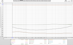
I've included a fully range distortion plot sweep of the Wolverine EF3-4. No bandwidth limiting, full range to 384khz
The plot is 25v or 80WRMS driving an 8 ohm load.
Hence. The optimum class AB quiescent bias for a conventional output stage is that the amount of current that produces a voltage drop of approximately 26 mV across each of the output emitter resistors.
However, Real-world factors like ohmic emitter and base resistance in the output transistors, and the resistance of base resistors tend to reduce that value.
Furthermore in practice using base resistors of 2.2 ohms and 0.22 ohm emitter resistors lower bias voltages than the 26mv seam to produce lower distortion. For example in the range 18-22mv one thing was very clear once the bias becomes to low the crossover distortion increase rapidly. So even though lower crossover distortion can be achieved with 18-20mV its safer to aim for 22-24mv to avoid those increased conditions.
I've included a fully range distortion plot sweep of the Wolverine EF3-4. No bandwidth limiting, full range to 384khz
The plot is 25v or 80WRMS driving an 8 ohm load.
Attachments

The Ic vs Vbe relationship holds to within 1% over six decades of Ic current in commercial log amps that exploit this (see for example the AD534 log amp). Under laboratory conditions, it can be shown to hold to 9 Orders of magnitude. From this you can draw the conclusion that a bipolar junction transistor is a voltage controlled device and not as is often stated, a current controlled device. The Ib vs Ic relationship by contrast is quite sloppy and nowhere near as accurate (maybe to within 10% over 2-3 orders of magnitude - but very device specific unlike the Ic vs Vbe relationship).Hi @EdGr I thought that the relationship between Vbe and Ic only followed approximate relationship
Ie = Is * exp (Vbe/Vt)
for small signal analysis and once the collector current reaches approximately 1A is starts to behave linearly, like a resistance.
This link may also be of interest
Small signal analysis of a BJT
Last edited:
For the Oliver voltage, you should include the re’ * Ic voltage drop as part of the .026 mV figure. As mentioned in my earlier post, the distortion profile is quite flat between c. 13mV and about 26mV (measured on many prototypes 🙂 ). However, in most modern feedback amplifiers, and especially those using TMC or TPC, there’s plenty of feedback available to reduce OPS distortion to negligible levels so I would not agonise over it.
Yes exactly, Thanks for your input.For the Oliver voltage, you should include the re’ * Ic voltage drop as part of the .026 mV figure. As mentioned in my earlier post, the distortion profile is quite flat between c. 13mV and about 26mV (measured on many prototypes 🙂 ). However, in most modern feedback amplifiers, and especially those using TMC or TPC, there’s plenty of feedback available to reduce OPS distortion to negligible levels so I would not agonise over it.
I would say trying to eliminate crossover distortion at 1k is completely pointless as there is enough feedback to eliminate it.
But at 20k you certainly can benefit a little from setting an optimal bias level.
Most amps have lower feedback at 20k and that is also an important factor in HF distortion. With TMC and TPC the loop gain is pretty much flat out to 20k+. if you do the math, the diffferrnce between the .026mV Oliver voltage and your figure of 18-22 mV is made up primarily from the re’ * Ic term.
🙂
🙂
Looking at those references, the schematics seem to retain the degenerating resistors on the emitters/drains of the output devices. I think the point here is to look at what you can get without the degeneration. Not as useful for Bipolars with exponential character, but very desirable with Fets and their square law character.
I am still writing my article. 😉
I added a MOSFET graph. Scroll to the bottom.
The bipolar transistor won on distortion, but both are pretty linear.
Ed
I added a MOSFET graph. Scroll to the bottom.
The bipolar transistor won on distortion, but both are pretty linear.
Ed
Nelson Pass - The cancellation of the square term happens only as long as both MOSFETs are conducting. I stopped the simulation at 0.4A because that bias is burning 75% of the maximum dissipation. I wanted the analysis to remain relevant to Class AB.
Ed
Ed
stuartmp - Your measurement of the Wolverine's distortion has caused me to re-think my approach to amplifier design.
The measured 0.00024% THD is lower than I thought possible. It is so low that the analyzer has to fish the distortion products out from below the THD+noise floor. Both the Wolverine and the analyzer are performing incredible feats of engineering.
The low distortion is achieved through high global feedback (I estimate ~50dB). The Wolverine has high-open loop gain with effectively one more gain stage than my amplifier. The Wolverine is quite similar in design to an IC op-amp. The high negative feedback is made possible by fast power transistors (Ft=30MHz).
In contrast, my amplifier traces its origins to the "Low TIM" school of design. I designed each stage to be highly linear and applied only 23dB of global feedback. Linear stages are possible for all but the last which has to handle huge current swings. The open-loop gain is moderate and the frequency compensation is mild (dominant pole >20KHz).
This is a conservative design because it can run open-loop and still be a respectable amplifier. The downside is that not much global feedback is available to linearize the last stage's exponential.
I estimate that my design achieves 0.015% THD. This is below the threshold of audibility but would be measurable without a sophisticated analyzer.
The question in my mind is what downsides are there to pushing distortion much lower through global feedback? I think that feats of engineering are fine only as long as they do not worsen other attributes of the design. I think I am going to stick with the low-global-feedback approach unless I can convince myself that applying more feedback has no downsides.
Ed
By using SPICE I have found that optimal bias is depending on the power devices.
Some have optimall bias 50mA other have optimal bias 100mA.
I am talking about BJT power devices.
Some have optimall bias 50mA other have optimal bias 100mA.
I am talking about BJT power devices.
lineup - That is consistent with my analysis. The voltage across the emitter resistors should be ~20mV.
Ed
Ed
- Home
- Amplifiers
- Solid State
- Class AB Biasing (article)