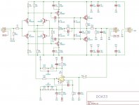
Your DOA33 does run within 25 V - 35 V very well.
To increase the supply voltages significantly, you would have to replace BC413 and BC415.
3 x 150 Ohm-resistors set the current. You could the middle one replace by trimmer (500 Ohm), as example.
I would remove the last two diodes 1N914 (feedback), it will sound much cleaner.
To get more "smack" (sound) connect emitter-base MJE182 and emitter-base MJE172 - per resistor or wire. Better solution than the two 1N914.
You could replace both R33 (emitter-resistors) per other values to modify the sound: the higher the more naturalistic. The lower the duller, more brittle, tighter.
Attention: this one is a push-pull-design, 3 (1/2) steps: this one is not to use to listen music;-)-;
Last edited:

i have this doa33 circuitYour DOA33 does run within 25 V - 35 V very well.
To increase the supply voltages significantly, you would have to replace BC413 and BC415.
3 x 150 Ohm-resistors set the current. You could the middle one replace by trimmer (500 Ohm), as example.
I would remove the last two diodes 1N914 (feedback), it will sound much cleaner.
To get more "smack" (sound) connect emitter-base MJE182 and emitter-base MJE172 - per resistor or wire. Better solution than the two 1N914.
You could replace both R33 (emitter-resistors) per other values to modify the sound: the higher the more naturalistic. The lower the duller, more brittle, tighter.
Attention: this one is a push-pull-design, 3 (1/2) steps: this one is not to use to listen music;-)-;
Attachments
May be, 2sc3421 and 2sa1358 are wonderful choice. May be not very liveful, not very large, a bit artificial over clear colors, like dollhouse, very disciplined.I will use 2sc3421 2sa1358 instead of mje172/78View attachment 1102577View attachment 1102578
I would replace Q5 and Q6 with the same types as Q7 and Q8. To get less differences of "character" of parts in both halfwaves, in both strands of amps - to get more harmonic and cleanness in sound. (Or Q6 the same as Q1 and Q3, Q5 the same as Q2 and Q4)
MJE172/182 I did not hear yet.
I would remove C7, C8, C11, C12. Without replacement.
Last edited:
Many manufacturers. Many characters. I have listen many types.i used to 92s bc550c bc560c
A picture is often worth 1,000 words. You will probably find a video like this short example is enough to gain some clear understanding. Note that it's a US video and the primary windings are connected in parallel for 115 VAC. Wiring the primary windings for use in the UK, is in series for 230VAC and the sense or winding direction of the windings on the core really matters - follow the guide covering the wire colour code in the sales or packing info:
Last edited:
Should be possible to drive speakers with this: replace output resistors by 1 Ohm or 0,47 Ohm types. Adjust the current.
Without any further preamps or so on!
Maybe the best way to listen music with pp-transes-amps;-)
Without any further preamps or so on!
Maybe the best way to listen music with pp-transes-amps;-)
What did you replace Q5 and Q6 with Q7 and Q8?May be, 2sc3421 and 2sa1358 are wonderful choice. May be not very liveful, not very large, a bit artificial over clear colors, like dollhouse, very disciplined.
I would replace Q5 and Q6 with the same types as Q7 and Q8. To get less differences of "character" of parts in both halfwaves, in both strands of amps - to get more harmonic and cleanness in sound. (Or Q6 the same as Q1 and Q3, Q5 the same as Q2 and Q4)
MJE172/182 I did not hear yet.
I would remove C7, C8, C11, C12. Without replacement.
Two half-waves but including two times the same character of two different parts, not 4 characters of 4 different parts: more harmony, cleanness, less noise, differences.What did you replace Q5 and Q6 with Q7 and Q8?
The same "character" of sound. Result of "streaming", "floating" - "current" does not describe the process. We have to understand "current": through materials, forms, modulated by resonances of materials...: same parts - nearly the same characters. different parts - very very different characters.
The ear does detect not "waves" only or amplitudes;-) The ear does detect differences at first. The ear does detect very very complex differences: signals. A measure per looking (oscilloscope) does not represent the audible character of parts and circuits and more. Not a bit. Zero!
;-)What did you use instead of 2n5210 2n5087?View attachment 1103228
I would decide by hearing.
...
I would use a single ended;-)
...
I would use a one-step-se: "single gain"-)
...
I would use not a pcb - then;-)
The datasheets say yes: 40 V no problem. But the BC-types could have higher Vce-values: BC 546/BC 556.I used bc550c bc560c from q1 to q6. i used 2s3421 2sa1358 at exit.
Should I run it at 40vdc?
View attachment 1104349
At moment I would suggest MPSA44/MPSA94, BF420/BF421 too. Recently tested. Belong to the 10% suitable for audio. In my house;-)
Yes. Same psu/s for all, if possible.I can get 33 v from the 4b stt of the doa33 that I will use with my 4b sst amp circuitView attachment 1104385View attachment 1104386View attachment 1104387
In your case: this are TWO separate half-waves-amps and TWO separate psus; the most cases.
I am pretty sure, the power-transes do not sit at ONE point of circuit. The usual mistake, because circuit is not understood.
- Home
- Amplifiers
- Solid State
- Class A board DOA33. PSU Help!