.
Some analyses
of Tyimo Choke Loaded Class A
Single IRFP240 MOSFET amplifier
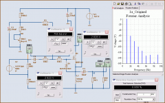
Fourier Analysis, Harmonics spectrum
at 1 Watt RMS into 8 Ohm
Looks nice.
The power consumption for this first is:
755 mV / 0.54 Ohm
which gives like 1.5 Ampere
when using one PSU 14.5 VDC
(Power supply Transformer is one Big 9 VAC or one Smaller 12 VAC ???)
What is it Tyimo
Shows very nice falling hramonics.
THD is below 0.09 % 😎 not bad!
Gain is low .. below x1
/lineup - Investigations In Audio
Some analyses
of Tyimo Choke Loaded Class A
Single IRFP240 MOSFET amplifier
Fourier Analysis, Harmonics spectrum
at 1 Watt RMS into 8 Ohm
Looks nice.
The power consumption for this first is:
755 mV / 0.54 Ohm
which gives like 1.5 Ampere
when using one PSU 14.5 VDC
(Power supply Transformer is one Big 9 VAC or one Smaller 12 VAC ???)
What is it Tyimo
Shows very nice falling hramonics.
THD is below 0.09 % 😎 not bad!
Gain is low .. below x1
/lineup - Investigations In Audio
Attachments
Hi Lineup!
Why we aren't in the Pass forum?!?
Greets:
Tyimo
Yes!😀Looks nice.
200VA 12Vdcwhen using one PSU 14.5 VDC
(Power supply Transformer is one Big 9 VAC or one Smaller 12 VAC ???)
What is it Tyimo
Oh yeah!😀Shows very nice falling hramonics.
THD is below 0.09 % not bad!
It needs a good and high gain tube preamp as you know... 🙂Gain is low .. below x1
Why we aren't in the Pass forum?!?
Greets:
Tyimo
I have already been too much in Pass Labs.
I am only guest occational there. There are other that are more welcome ...... ... ...
One country can only have 1 King.
Two Kings are too much for any regime 😉
SEWA = pass
pass = OTA also by Mads_K
F5 = mosfet in pass labs
B1 = in pass labs
... now is the time Solid State transistor forum
learns how to use HEXFET!
Not only Bob Cordell and the big guys ... should learn this.
Nelson Pass is good with HEXFET from IRF
But think if they learn in here in Solid State.
If they will be thought how to use MOSFETs/HEXAGONAL Structures Die
And so we will make better amps than Nelson Pass
at about year 2015.
This is my hope. We can do it!
When Nelson Pass and Me and John 'jfet' Curl are dead 58, 68 years old already)
we need a few to be able to take over the inheritaged knowledge.
Two very promising for future are: Tyimo & Keantoken(16)
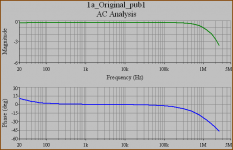
IRFP240 choke loaded AC Analysis
.
Here is AC analysis.
Impressive 😎
As my first setup of your Real Circuit shows:
2.2 MHz has rolloff -3 dB
2.3 MHz something for -45degrees Phase .. almost the same.
.. I could have a guess it has been trimmed, for this?
One reason this amplifier can be so fast,
is because the Voltage gain is low. Below 1.
This is one benefit from avoid un-necessary high gains
.. that the bandwidth can stay high.
In short, very good ac behavior and phase.
Superior to many other power amplifiers, I would say.
Attachments
Hi Lineup!

I am waiting meanman64's listening impressions. He is also biulding my amp.
Greets:
Tyimo
Oh no. I am under educated and shy..Two very promising for future are: Tyimo & Keantoken(16)
No, It is only tuned for musicality... I could have a guess it has been trimmed, for this?
Yes, and it has ZERO NFB.One reason this amplifier can be so fast, is because the Voltage gain is low. Below 1.
Yes and thanks!In short, very good ac behavior and phase.
Superior to many other power amplifiers, I would say.
I am waiting meanman64's listening impressions. He is also biulding my amp.
Greets:
Tyimo
Did you have a particular part in mind for L2? The reason I
ask is I saw a little discussion on Tubecad about the fact
that most chokes unless made for audio use distort AC a lot.
Then the author recommends adding a air core in series with
the iron core choke. The author compared this to adding
a film bypass cap for an electrolytic cap. Here is one example
of someone doing this.
Attachments
Ummm... aaaaa... Nelson Pass published this idea with Mosfets I think like 20 years ago now... then he did the Zen... I did my DC coupled SE Mosfet, then Nelson did a ton more, and I didn't...
😀
_-_-bear
😀
_-_-bear
I think it's just going to take a big gapped core. 120mH at an amp and a half is a tall order. Probably not impossibe, but beware of sticker shock.
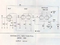
This is a real clever schematic...congratulations if you did it Lineup
of course, we cannot be original as we are in this world of fast coomunications... this idea, the choque coupling, remembers the amplifiers from the fifties (great times).
Into the fifties they used a transformer primary as the transistor or tube load, and the secondary was to the speaker.
this one is nice...only 1.5 amperes.... low voltage....low power consumption and around 25 percent efficiency.... good idea..this one is very interesting.... post the complete schematic please.
I know it is impossible to be the first to have ideas...now a days we can only produce Frankensteins products..as even if we create something, it belongs to mankind...someone had the same idea..or something alike, years or decades before.... hard to discover things now a days.
Congratulations...lovely one.
Carlos
Did you have a particular part in mind for L2? The reason I
ask is I saw a little discussion on Tubecad about the fact
that most chokes unless made for audio use distort AC a lot.
Then the author recommends adding a air core in series with
the iron core choke.
L2 is a gaped iron core.
Yes, the air core measures better on paper, but in the reality you would lose the power efficiency because of the very high Rdc of the air core. You don't need to care about the distorsion of a good gaped iron core.
Tyimo
This is true.
Air core need be fairly large to give 120mH
.. and while still keeping Rdc low
For a true aircore we need such thick wire.
One ironcore with a gap is a good compromise.
Other alternative would be to find a suitable ferrit toroid core.
There are different types with different sizes and different L/turn value.
But not always easy to find or to know which toroid would be the right one.
I am certainly no expert on wiring inductors for different tasks.
Tube people knows much more about these things.
They are customed to use output and/or input transformers.
Uncovered schematic please lineup, the one you have posted is covered
partially with the instruments.... post a new schematic if you want to share this lovely circuit.
Do you think it can operate with 750 miliamperes?...say, adjusting the circuit to this current. in my imagination those field effects works better with that current.... with 1.5 amperes and higher they start to muffle the trebles as i could see in my home.
regards,
Carlos
lineup said:
Other alternative would be to find a suitable ferrit toroid core.
What? 😱
Re: Uncovered schematic please lineup, the one you have posted is covered
I also have build this amp and I can say that the treble isn't muffled at all with 1,5 amperes current.That's what I think.It's like Tyimo is saying I need to post my impression of this amp.For the time that I had listen to the amp i must say very clear hights and tight bass.Compaired with my Zen amp much brighter treble not muffled at all.New sound impression will follow.
Hi Carlos,destroyer X said:
partially with the instruments.... post a new schematic if you want to share this lovely circuit.
Do you think it can operate with 750 miliamperes?...say, adjusting the circuit to this current. in my imagination those field effects works better with that current.... with 1.5 amperes and higher they start to muffle the trebles as i could see in my home.
regards,
Carlos
I also have build this amp and I can say that the treble isn't muffled at all with 1,5 amperes current.That's what I think.It's like Tyimo is saying I need to post my impression of this amp.For the time that I had listen to the amp i must say very clear hights and tight bass.Compaired with my Zen amp much brighter treble not muffled at all.New sound impression will follow.
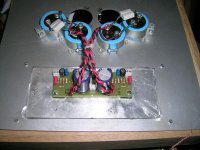
Attachments

I would do this as a balanced design (with a center-tapped choke), that would really make choke design less delicate (no/little DC)
Re: Re: Uncovered schematic please lineup, the one you have posted is covered
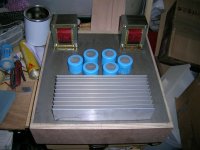
Oriented such a way your big heatsink is useless, unfortunately. With such spacing between fins it was designed for a free convection cooling, so hot air going up should flow in parallel with fins. If you leave it as is, prepare to keep your amp standing on it's side, for cooling purposes.
meanman1964 said:
Hi Carlos,
I also have build this amp and I can say that the treble isn't muffled at all with 1,5 amperes current.That's what I think.It's like Tyimo is saying I need to post my impression of this amp.For the time that I had listen to the amp i must say very clear hights and tight bass.Compaired with my Zen amp much brighter treble not muffled at all.New sound impression will follow.
Oriented such a way your big heatsink is useless, unfortunately. With such spacing between fins it was designed for a free convection cooling, so hot air going up should flow in parallel with fins. If you leave it as is, prepare to keep your amp standing on it's side, for cooling purposes.
Thank you Meanman...can you please send me the schematic?
I think Lineup is not reading my messages...so..please, send me the schematic.
panzertoo@yahoo.com
regards,
Carlos
I think Lineup is not reading my messages...so..please, send me the schematic.
panzertoo@yahoo.com
regards,
Carlos
Tyimo said:
L2 is a gaped iron core.
Yes, the air core measures better on paper, but in the reality you would lose the power efficiency because of the very high Rdc of the air core. You don't need to care about the distorsion of a good gaped iron core.
Tyimo
DCR <2R for 100mH is not all that bad, and that you can sure have from an air core inductor.
...and the loss that remains, is fairly linear.
Magura 🙂
- Status
- Not open for further replies.
- Home
- Amplifiers
- Solid State
- CHOKE Loaded MOSFET, easy to build