C'mon Carlos, don't you see what is missing?.... Nothing is missing!
Plain old AC-coupled follower into an AC constant current source (the choke) with mixed bias (DC voltage bias on the gate plus some source self biasing from the DC-R of the choke).
- Klaus
Plain old AC-coupled follower into an AC constant current source (the choke) with mixed bias (DC voltage bias on the gate plus some source self biasing from the DC-R of the choke).
- Klaus
And by the way:
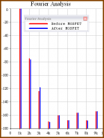
Most MOSFET models tend to stink, with a notable exception: the IRFP244 (very close to the 240) from andy_c.
Distortion sims have to be take with very much care, although followers are not that critical....
- Klaus
Most MOSFET models tend to stink, with a notable exception: the IRFP244 (very close to the 240) from andy_c.
Distortion sims have to be take with very much care, although followers are not that critical....
- Klaus
Re: Re: Re: Uncovered schematic please lineup, the one you have posted is covered
I will keep it in mind and do some temperature tests.For know this is a prototype case.Wavebourn said:
Oriented such a way your big heatsink is useless, unfortunately. With such spacing between fins it was designed for a free convection cooling, so hot air going up should flow in parallel with fins. If you leave it as is, prepare to keep your amp standing on it's side, for cooling purposes.
Hi Lineup!
You need a gapped one! Ferrit powder cores are too small and weak. A normal toroid is good but with airgap.
With C-cores and EI are easy and good to make the chokes.
Tyimo
Other alternative would be to find a suitable ferrit toroid core.
You need a gapped one! Ferrit powder cores are too small and weak. A normal toroid is good but with airgap.
With C-cores and EI are easy and good to make the chokes.
Tyimo
Wavebourn!
Yes it is true, but the amp is (everyway😀 ) cool. It doesn't need too big heatshink. I built 4 amplifier with this arrangement and all are working very fine!! Meanman needn't care about it.
Tyimo
Oriented such a way your big heatsink is useless, unfortunately. With such spacing between fins it was designed for a free convection cooling, so hot air going up should flow in parallel with fins. If you leave it as is, prepare to keep your amp standing on it's side, for cooling purposes.
Yes it is true, but the amp is (everyway😀 ) cool. It doesn't need too big heatshink. I built 4 amplifier with this arrangement and all are working very fine!! Meanman needn't care about it.
Tyimo
Meanman1964!
Tyimo
Don't forget that the sound will be even better with a good tube preamp!😉New sound impression will follow.
Tyimo
Re: Thank you by the schematic Patrick

I hope I ain't getting trouble by giving it to youdestroyer X said:
here is the schematic Patrick sent to me by request..because Lineup have not posted.
regards,
Carlos
If you don't want troubles I can design an amp with the same functionality, but better results. 😀
Nobody patented choke loaded source follower, I believe. 😉
Nobody patented choke loaded source follower, I believe. 😉
Wavebourn said:If you don't want troubles I can design an amp with the same functionality, but better results. 😀
Nobody patented choke loaded source follower, I believe. 😉
For me it's something like having respect for the person that made the schematic
🙂 🙂
Wavebourn!
You are wrong!
Pathos Audio patendted the "Inpol" topology!
😀
Tyimo
Nobody patented choke loaded source follower, I believe.
You are wrong!
Pathos Audio patendted the "Inpol" topology!
😀
Tyimo
For me it's something like having respect for the person that made the schematic
Thank you Meanman1964! You are very kind.🙂
Tyimo
Tyimo said:Wavebourn!
You are wrong!
Pathos Audio patendted the "Inpol" topology!
😀
I mean a different topology. 😀
Than it is O.K.I mean a different topology.
You don't need to pay the copy right....😀
Tyimo
I've just done a similar amp with 5687 valve input stage , 150mH choke and IRFP150 mosfet running on a 14V rail at 1.5A . In a choke loaded design the output capacitor becomes reverse-biased with reference to 0V on higher voltage swings . Is this an issue ?
cheers
316A
cheers
316A
Would anybody be so kind to educate an ignorant diyer about how the choke loading works? (references and links are very welcome 🙂 )
Btw I'm a bit perplexed about the 8.2R resistor from input ground to output ground. What's its purpose?
Thanks very much to anyone willing to answer.
Ciao!
Massimo
Btw I'm a bit perplexed about the 8.2R resistor from input ground to output ground. What's its purpose?
Thanks very much to anyone willing to answer.
Ciao!
Massimo
antomas said:Would anybody be so kind to educate an ignorant diyer about how the choke loading works? (references and links are very welcome 🙂 )
Btw I'm a bit perplexed about the 8.2R resistor from input ground to output ground. What's its purpose?
Thanks very much to anyone willing to answer.
Ciao!
Massimo
Look here and you've your answer http://www.diyaudio.com/forums/showthread.php?s=&threadid=66822&perpage=10&pagenumber=85 see post 843
antomas said:Would anybody be so kind to educate an ignorant diyer about how the choke loading works?
Choke loading works best with ferret cores. You must insert the ferret at an early age and be patient. And you must use a small enough coil so that the ferret chokes properly as it grows.

Attachments

- Status
- Not open for further replies.
- Home
- Amplifiers
- Solid State
- CHOKE Loaded MOSFET, easy to build