The PSUs are MeanWell RS-100-24 (have four of those). And yes it will be experimental. The idea using the 4-pole caps was to have a very low impedans PSU so peak currents are delivered by the caps. The idea using the DC serial choke was try to "hide" the caps from the SMPS.
Well yes... but:
A big cap will load the SMPS as it tries to recharge it, a smaller cap will recharge much quicker because the cap is essentially being charged from a high frequency source (that's rectified).
All that is confused even more by the SMPS having its own regulation built in and large caps will alter the time contant... all I can say is you must try it under known conditions.
I would rig a switched load up which is dead easy with any suitable power transistor arranged as a constant current sink. Just pulse the load at some test frequency and suitable duty cycle (use a 555 timer chip running from a PP3 battery for that). That way you get absolutely consistent results and you can look at the ripple with different caps and chokes.
In high voltage tube psu I think a rule of thumb is 1k Ohm bleeder pr Henry in the choke. You can measure v out with different bleeder values and chose a value which keep the v out ( when psu is loaded only by the bleeder) comfortably low
I have the ACA and I also have a square wave generator so I could load ACA with 8 ohm and then power it first with just pure Meanwell and measure etc. Then I could load with caps of difference sizes to see what happens. I don't have the 11 mH chokes yet. But I have large 50 mH 25 kg (73 mOhm) chokes used for MoFo I could try with. Think I have developed a special habit for large chokes 🙂
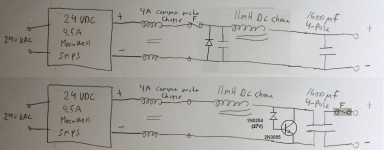
Yes, fuse is after caps to have most protection of the fuse so the fuse don't have to take the "kick in" current of the caps…...that is the idea. A large zener sounds like the most simple solution.
Now I added 4 x 30V zener to my order. It is a good feature that you can make an attachment order as long as first order is not shipped…...but also cost a lot of money. This attachment was no. 4.....so I have given myself a lot of Christmas gifts.
I don't know what a large zener is......the ones I ordered was 12.5 W types. They have M4 thread (hope they are regarded as large in this context). So now I have bleeder resistor, Varistor, Zener. These 3 together should do it.....
I don't know what a large zener is......the ones I ordered was 12.5 W types. They have M4 thread (hope they are regarded as large in this context). So now I have bleeder resistor, Varistor, Zener. These 3 together should do it.....
...to "eat" the energy of the choke if fuse blows to protect the caps from high voltage....
How big is the cap??
For any likely value I get a "surge" like 5 Volts. Your cap surely has 5V margin. For larger 10,000uFd cap the surge is 2V. 100uFd the surge is 16V, to 39.73V.
If these are e-caps they will stand considerable transient voltage. An 11mH choke is not about to blow-up a large e-cap. If choke DCR is 0.1 Ohm the swings start to decay visibly in 100mS, down to 1V excess in 400mS.
Attachments

Last edited:
It will be two 4-pole Jensen in parallel. Each are 8200 uF / 64 VDC. They can usually take a bit of surge voltage. So you mean that the 11 mH choke with 1.5A DC current has not enough energy to destroy the caps…...can see you have some simulation...….
I could not see the DC resistance for the choke in data sheet. It is only a 1kg (0.25 kg copper) choke rated 5.7A DC.
So 1K bleeder resistor + power zener just to be sure...I should be ok.
Just for "fun"......if choke was 1H......how would simulation look like?
So 1K bleeder resistor + power zener just to be sure...I should be ok.
Just for "fun"......if choke was 1H......how would simulation look like?
Hello,
Unless you have the right gear and the knowledge to test what the effect would be when you add an lc network at the output of the smps i would not even try it. There are even regulator circuits which are much more basic that get worse by adding parts at the output. The fact you have them in stock and they are high quality parts does not mean they will give an improvement where ever you use them.
Designing an smps seems to be a tricky thing if you wanna use it for audio. Making a brand name product better by adding some parts maybe could be done if a competent person tells you there is some noise at the output which can be filtered to make it better for audio. They would give you the values to compose an lc filter and probably also tell you what kind of capacitor you would need to filter the hf garbage i presume.
Greetings, Eduard
I am able to measure distortion on amp via FocusRite sound card and dedicated software (REW). So it will be a interesting exercise. It is quite normal to put a common mode choke after SMPS. This could be option 1 to do that and then noting else. As it is a Class A power amp the current draw is quite constant. Then I can experiment with how the SMPS behave if load is capacitive and if it goes into protection etc. It is this one in 24 VDC:
https://docs.rs-online.com/f39d/0900766b81621e7a.pdf
It could be a cheap way to get a good audio PSU for constant current class A amp. It solves a lot of problems. I also see this like an experiment and "DIY fun".
https://docs.rs-online.com/f39d/0900766b81621e7a.pdf
It could be a cheap way to get a good audio PSU for constant current class A amp. It solves a lot of problems. I also see this like an experiment and "DIY fun".
Hello,
From what i read so far i know that some of these smps supplies add a kind of sonic signature to your device that is not always nice. Sometimes a simple lclc or clc supply will not have spectacular specs but you can listen to it for hours.
Greetings, Eduard
From what i read so far i know that some of these smps supplies add a kind of sonic signature to your device that is not always nice. Sometimes a simple lclc or clc supply will not have spectacular specs but you can listen to it for hours.
Greetings, Eduard
Normally I am also "old school" regarding PSU for audio but when I see distortion measurements from people that use SMPS I don't see the "switching noise" people talk about but I see measurements that is nearly 100% free from 50/100 Hz or 60/120 Hz noise. People who use normal CRC filtering showing their distortion measurement has always quite large "spikes" at 50/100 or 60/120 Hz but people never question that?
Now with LCLC or RCLC these "spikes" can be reduced a lot. But the idea was to have the best of both worlds using the SMPS with additional filtering. I want to place the 4-pole caps very close to amp board to have a short wires to it to get a PSU seen from amp with very low impedance but SMPS should "see" a bit higher impedance so internal control is not "damaged".....that was the idea using the DC-choke…..to "smooth" the current draw from SMPS a bit.
Now with LCLC or RCLC these "spikes" can be reduced a lot. But the idea was to have the best of both worlds using the SMPS with additional filtering. I want to place the 4-pole caps very close to amp board to have a short wires to it to get a PSU seen from amp with very low impedance but SMPS should "see" a bit higher impedance so internal control is not "damaged".....that was the idea using the DC-choke…..to "smooth" the current draw from SMPS a bit.
I found here a bit of information about SMPS filtering:
https://www.analog.com/media/en/tec...gulator-noise-reduction-with-an-lc-filter.pdf
…..which could indicate I am on right track.....at least as an experiment. But now topic is more how to filter a SMPS instead of just "choke bleeder".....which seemed to be solved.
https://www.analog.com/media/en/tec...gulator-noise-reduction-with-an-lc-filter.pdf
…..which could indicate I am on right track.....at least as an experiment. But now topic is more how to filter a SMPS instead of just "choke bleeder".....which seemed to be solved.
- Home
- Amplifiers
- Power Supplies
- Choke bleeder resistor