Admitted, the title sounds weird. Actually, we already have a thread concerned with the use of LM1875, in particular with more in parallel, as power stage in a composite amplifier. The final aim there is to test such a composite amplifier in BTL-configuration. Without being aware when I bought my LM1875, I ended up with specimens that are probably “fake” and do not behave fully as LM1875 ICs delivered straight from TI. My “fake” LM1875 sometimes perform more like TDA2050. As the TDA2050 is pin-compatible with the LM1875 and their specifications are pretty much alike, this existing thread also include the use of TDA2050. ST no longer produces TDA2050 but a company in Taiwan, Unisonic, produces a version called UTC-TDA2050V that seems to perform very well and can be bought at a very good price. Such is for the existing thread.
Work with LM1875 and TDA2050 in the existing thread got to a point where it was difficult to disregard that other chip-amps may also be very suited for composite amplifiers. In particular for higher power levels. In posting #510 ( LM1875 in parallel configuration and used in a composite amplifier. ) of the existing thread, a scheme was drafted mentioning a plurality of chip-amp candidates.
Before a chip-amp is used in a composite amplifiers, its behavior should be investigated such that an implementation of the chip-amp is used in the composite amplifier that is 100% predictable and reliable. This sounds trivial but even the well known LM1875 showed some characteristics, like self-oscillation and de-rated operational limits, that took most of the time before the complete amplifier performed well. Another problem related to use of chip-amps at a gain below the minimum gain specified in the datasheet.
For other chip-amps than LM1875/TDA2050, where should the results from investigations be disclosed? The existing thread is already becoming comprehensive with LM1875/TDA2050 issues, parallel-coupling issues, controlling OP-AMP issues etc. Therefore, the present thread is started with the purpose to disclose experimental results and considerations relating to these further chip-amps, when using them below the minimum gain, when connecting them in parallel, when improving stability, when protecting them from overload etc.
FF
Last edited:
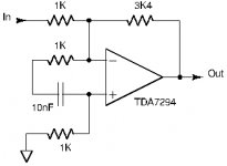
I got curious to see how a TDA7294 would be able to perform so I prepared a simple test-board as an inverting coupling.
The board worked as such though the output would show importantly asymmetrical clipping. That asymmetrical clipping related to a flawed performance of the boot-strap supply to the high-side power transistor such that the power transistor never got a boosted voltage and could not be pulled up to the level intended. The TDA7294 IC I used had a defect.
Before changing the IC, I tested it for stability with a gain of -3.4 (minus for inverting configuration). That is much below what is stated to be the minimum gain in the TDA7294 datasheet. Probably because of this low closed-loop gain, the output would show fine oscillations when exceeding a certain negative level. These oscillations can be seen in posting #528 ( LM1875 in parallel configuration and used in a composite amplifier. ) of the other thread. Notice the oscillation on the lowest part of the curve.
Using that would not be a success. So, I had to try to remove the oscillation while still maintaining the gain of -3.4.
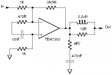
I added an RC-string between the inverting and non-inverting inputs of the TDA7294. With quite some attempts using varying values for the “C” and the “R”, I managed to find values that seem to do the trick. These values were 10nF and 1K.
Picture 1: The schematic (essential part) including the RC string.
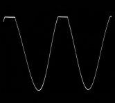
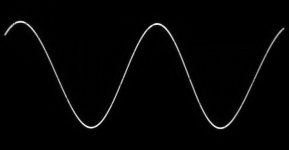
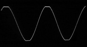
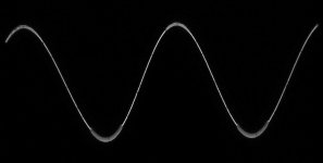
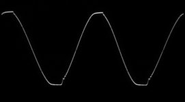
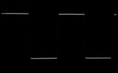
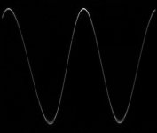
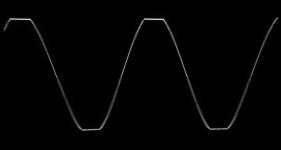
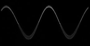
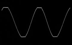
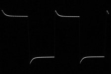
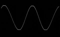
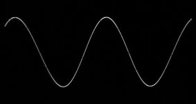
Picture 2: Sine-wave (clipping at the top due to defect chip) at 1KHz, 35Vpp amplitude, 8 Ohm load. Notice that the oscillation has disappeared.
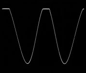
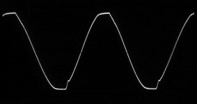
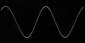
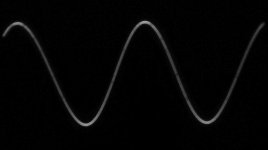
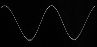
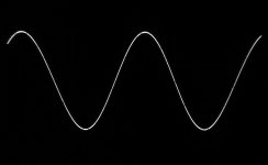
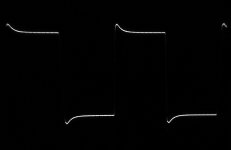
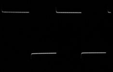
Picture 3: As above but at 20KHz. Same amplitude and load. Still no oscillation.
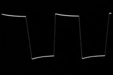
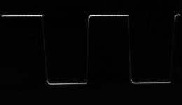
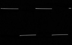
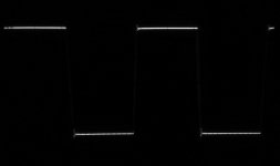
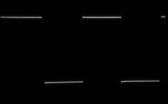
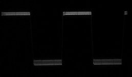
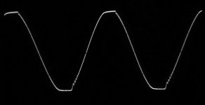
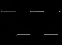
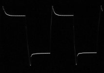
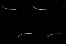
Picture 4: Square-wave at 20KHz. 20Vpp amplitude and 8 Ohm load.
It seems that such an RC-string can counter-act oscillation with low closed loop-gain.
I will now change the IC to a TDA7293 such that output clipping is symmetrical and test again.
The board worked as such though the output would show importantly asymmetrical clipping. That asymmetrical clipping related to a flawed performance of the boot-strap supply to the high-side power transistor such that the power transistor never got a boosted voltage and could not be pulled up to the level intended. The TDA7294 IC I used had a defect.
Before changing the IC, I tested it for stability with a gain of -3.4 (minus for inverting configuration). That is much below what is stated to be the minimum gain in the TDA7294 datasheet. Probably because of this low closed-loop gain, the output would show fine oscillations when exceeding a certain negative level. These oscillations can be seen in posting #528 ( LM1875 in parallel configuration and used in a composite amplifier. ) of the other thread. Notice the oscillation on the lowest part of the curve.
Using that would not be a success. So, I had to try to remove the oscillation while still maintaining the gain of -3.4.
I added an RC-string between the inverting and non-inverting inputs of the TDA7294. With quite some attempts using varying values for the “C” and the “R”, I managed to find values that seem to do the trick. These values were 10nF and 1K.
Picture 1: The schematic (essential part) including the RC string.
Picture 2: Sine-wave (clipping at the top due to defect chip) at 1KHz, 35Vpp amplitude, 8 Ohm load. Notice that the oscillation has disappeared.
Picture 3: As above but at 20KHz. Same amplitude and load. Still no oscillation.
Picture 4: Square-wave at 20KHz. 20Vpp amplitude and 8 Ohm load.
It seems that such an RC-string can counter-act oscillation with low closed loop-gain.
I will now change the IC to a TDA7293 such that output clipping is symmetrical and test again.
Attachments
Last edited:
following with interest! I think the TDA7293/TDA7294 is on paper the only chip which can compete performance wise with the LM3886, but it also has the unique master/slave option which will greatly simplify parallel operation. Let's see what team Europe can do!
following with interest! I think the TDA7293/TDA7294 is on paper the only chip which can compete performance wise with the LM3886, but it also has the unique master/slave option which will greatly simplify parallel operation. Let's see what team Europe can do![/QUOTE]
😀
FF - Fast forward
Turbowatch2 - turbo !!!.....what else
Fred - very good experienced diy
Hi FF
...With quite some attempts using varying values for the “C” and the “R”, I managed to find values that seem to do the trick. These values were 10nF and 1K.
if i look at your schematic -can i say the 1k and 10nF are a kind of "zobel network" ?? so the oscilating come from the fb resistor and gets away to the 1k to GND?
sorry my easy thinking🙄😉
chris
following with interest! I think the TDA7293/TDA7294 is on paper the only chip which can compete performance wise with the LM3886, but it also has the unique master/slave option which will greatly simplify parallel operation. Let's see what team Europe can do!
Two TDA7293 with the DMOS output stages connected in parallel can nominally surpass a LM3886 with a bit. At Reichelt, the TDA7293 is sold for 2.90 Eur, just below half of the price for an LM3886. Splitting the power loss and current between two chips leaves some advantage.
following with interest! I think the TDA7293/TDA7294 is on paper the only chip which can compete performance wise with the LM3886, but it also has the unique master/slave option which will greatly simplify parallel operation. Let's see what team Europe can do![/QUOTE]
😀
FF - Fast forward
Turbowatch2 - turbo !!!.....what else
Fred - very good experienced diy
Late in the afternoon I changed the TDA7294 for a TDA7293 with the expectation to solve the poor functioning of the voltage boot-strap. For those who are not familiar with the purpose of voltage-bootstrap, it is essentially a “flying capacitor” raising the voltage for the high-side power transistor temporarily above the supply rail voltage such that the power transistor can be driven closer to the positive supply rail.
For the TDA7294 used for a start, the boot-strap voltage was clamped, probably by the IC itself, to a value below the supply rail voltage in which case it has no effect. Clipping of the output transistors was very uneven with the high-side transistor clipping first.
Getting the solder out of the plated holes was not easy but I managed in the end. The TDA7293 was put in and the board ready for test. Without a load, I put power on and it functioned from first moment -but, the output clipped asymmetrically just as before with the TDA7294. Also with the TDA7293, the boot-strap voltage remained clamped to below the voltage of the positive voltage rail.
Exactly why it still does not function, I need to investigate tomorrow.
The advantage of the TDA7293 compared to TDA7294 is that TDA7293 has an intermediate output between the pre-amp part and the output power-stage such that it leaves further possibility to stabilize the chip for gains below what is recommended in the datasheet. That intermediate output is used for connection of output stages in parallel using the master-slave structure. Even if the boot-strap problem remains for the new TDA7293, stability tests can be carried out.
Hi FF
...With quite some attempts using varying values for the “C” and the “R”, I managed to find values that seem to do the trick. These values were 10nF and 1K.
if i look at your schematic -can i say the 1k and 10nF are a kind of "zobel network" ?? so the oscilating come from the fb resistor and gets away to the 1k to GND?
sorry my easy thinking🙄😉
chris
A logical assumption but not really the same function.
The zobel network (Boucherot Cell) serves to ensure low impedance damping of high frequency oscillation ( Boucherot cell - Wikipedia ). This increases amplifier stability.
The CR-string serves to transform a feedback signal, normally only entering the inverting input as a differential signal, partly into a common-mode signal for the two inputs. Some time ago we had an article (I believe) that discussed noise-gain and overall gain, and influence on stability.
When the feedback signal arrives at the inverting input, and no CR-string is used, this signal makes only the inverting input vary (not the non-inverting input) such that the feedback signal is a differential signal to the two inputs. The feedback signal counteracts the signal at the input in the manner negative feedback works. For such amplifiers, too much negative feedback (too little overall gain) can result in instability.
With the CR-string, a part of the feedback signal is passed-on to the non-inverting input as well such that the two inputs vary simultaneous and the feedback signal in part becomes a common-mode signal (the differential signal amplitude is reduced) . But, a common-mode signal is not amplified by the amplifier chip. The CR-string has frequency dependent impedance where most of the feedback signal is passed on to the non-inverting input as well at high frequencies and much less at lower frequencies, The result is that the feedback at low frequencies is harder than at high frequencies. If instability occurs because we apply too much feedback at higher frequencies, the CR-string creates a system with strong feedback (and low overall gain) at low frequencies but much less feedback at high frequencies such that instability is avoided.
Last edited:
A logical assumption but not really the same function.
The zobel network (Boucherot Cell) serves to ensure low impedance damping of high frequency oscillation ( Boucherot cell - Wikipedia ). This increases amplifier stability.
The CR-string serves to transform a feedback signal, normally only entering the inverting input as a differential signal, partly into a common-mode signal for the two inputs. Some time ago we had an article (I believe) that discussed noise-gain and overall gain, and influence on stability.
When the feedback signal arrives at the inverting input, and no CR-string is used, this signal makes only the inverting input vary (not the non-inverting input) such that the feedback signal is a differential signal to the two inputs. The feedback signal counteracts the signal at the input in the manner negative feedback works. For such amplifiers, too much negative feedback (too little overall gain) can result in instability.
With the CR-string, a part of the feedback signal is passed-on to the non-inverting input as well such that the two inputs vary simultaneous and the feedback signal in part becomes a common-mode signal (the differential signal amplitude is reduced) . But, a common-mode signal is not amplified by the amplifier chip. The CR-string has frequency dependent impedance where most of the feedback signal is passed on to the non-inverting input as well at high frequencies and much less at lower frequencies, The result is that the feedback at low frequencies is harder than at high frequencies. If instability occurs because we apply too much feedback at higher frequencies, the CR-string creates a system with strong feedback (and low overall gain) at low frequencies but much less feedback at high frequencies such that instability is avoided.
AAAAAh..... thanks.
Did you measure the overall frequency response with/without your Boucherot Cell?
AAAAAh..... thanks.
Did you measure the overall frequency response with/without your Boucherot Cell?
Not yet. My quick test of the TDA7294 showed oscillation when I connected the Boucherot Cell. So for a start I disconnected it.
My first concern was to make the boot-strap work such that I had a correct output. The boot-loader output (pin 12) did not work well so I used the regular output (pin 14) instead and the output became normal. Symmetrical clipping and clipping near to the rail voltages.
I will now start doing tests of the behavior, starting with a gain of -27 and going downward.
TDA7293
I made some tests with my TDA7293 test-board. With a simple inverting configuration using a 1K input resistor, I tested performance with gains from -27 and down to -2,5. The minimum gain for the TDA7293 is 26dB (20 times) according to the datasheet.
I used a regulated +/-24V supply voltage and a 4 Ohm load that would bring the peak currents in the load above 5A.
A preliminary positive aspect of the TDA7293 is that, with +/-24V supply and peak currents exceeding 5A in the 4 Ohm load, the output peak voltages go to 21V in both directions thus 3V below the supply rail voltages. That is better than for many chip-amps with bipolar output transistors. TD7293 uses DMOS output transistors. Further, the square-wave response generally looked good and well damped with a resistive load.
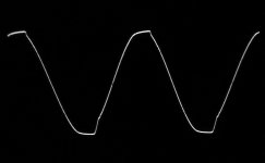
Less appreciated but as expected, with closed loop gains below what is recommended in the datasheet, oscillations appear on the output curve above a certain amplitude and in particular in the negative half-waves. And, the TDA7293 seems very sensitive to capacitive loading where even 10nF at the output for a start caused permanent (not amplitude dependent) oscillation.
-27 times gain, 4 Ohm load and +/24V supply, no Zobel network.
Picture 1: 1KHz, sine-wave, 20Vpp.
Picture 2: 1KHz, square-wave, 20Vpp.
Picture 3: 1KHz, sine-wave, clipping at 42Vpp.
Picture 4: 20KHz, square-wave, 20Vpp.
Picture 5: 20KHz, sine-wave, clipping at 42Vpp.
* Permanent oscillation with 10nF or 100nF at the output.
-10 times gain, 4 Ohm load and +/24V supply, no Zobel network.
Picture 6: 1KHz, sine-wave, 20Vpp.
Picture 7: 1KHz, square-wave, 20Vpp.
Picture 8: 1KHz, sine-wave, clipping at 42Vpp.
Continued...........
I made some tests with my TDA7293 test-board. With a simple inverting configuration using a 1K input resistor, I tested performance with gains from -27 and down to -2,5. The minimum gain for the TDA7293 is 26dB (20 times) according to the datasheet.
I used a regulated +/-24V supply voltage and a 4 Ohm load that would bring the peak currents in the load above 5A.
A preliminary positive aspect of the TDA7293 is that, with +/-24V supply and peak currents exceeding 5A in the 4 Ohm load, the output peak voltages go to 21V in both directions thus 3V below the supply rail voltages. That is better than for many chip-amps with bipolar output transistors. TD7293 uses DMOS output transistors. Further, the square-wave response generally looked good and well damped with a resistive load.
Less appreciated but as expected, with closed loop gains below what is recommended in the datasheet, oscillations appear on the output curve above a certain amplitude and in particular in the negative half-waves. And, the TDA7293 seems very sensitive to capacitive loading where even 10nF at the output for a start caused permanent (not amplitude dependent) oscillation.
-27 times gain, 4 Ohm load and +/24V supply, no Zobel network.
Picture 1: 1KHz, sine-wave, 20Vpp.
Picture 2: 1KHz, square-wave, 20Vpp.
Picture 3: 1KHz, sine-wave, clipping at 42Vpp.
Picture 4: 20KHz, square-wave, 20Vpp.
Picture 5: 20KHz, sine-wave, clipping at 42Vpp.
* Permanent oscillation with 10nF or 100nF at the output.
-10 times gain, 4 Ohm load and +/24V supply, no Zobel network.
Picture 6: 1KHz, sine-wave, 20Vpp.
Picture 7: 1KHz, square-wave, 20Vpp.
Picture 8: 1KHz, sine-wave, clipping at 42Vpp.
Continued...........
Attachments
-
 TDA7293_Gain10_1KHz_Clip42Vpp.jpg272.9 KB · Views: 126
 -
 TDA7293_Gain10_1KHz_20VppSQ.jpg160.4 KB · Views: 125
 -
 TDA7293_Gain10_1KHz_20Vpp.jpg200.4 KB · Views: 120
 -
 TDA7293_Gain27_20KHz_Clip42Vpp.jpg316.9 KB · Views: 521
 -
 TDA7293_Gain27_20KHz_20VppSQ.jpg360.5 KB · Views: 518
 -
 TDA7293_Gain27_1KHz_Clip42Vpp.jpg341.9 KB · Views: 526
 -
 TDA7293_Gain27_1KHz_20VppSQ.jpg339.5 KB · Views: 535
 -
 TDA7293_Gain27_1KHz_20Vpp.jpg300.2 KB · Views: 603
Last edited:
TDA7293
Continued from posting #12.
-10 times gain, 4 Ohm load and +/24V supply, no Zobel network.
Picture 9: 1KHz, sine-wave, fine oscillation before saturation/clipping.
Picture 10: 20KHz, square-wave, 20Vpp.
Picture 11: 20KHz, sine-wave, clipping at 42Vpp.
* Permanent oscillation with 10nF or 100nF at the output.
-5 times gain, 4 Ohm load and +/24V supply, no Zobel network.
Picture 12: 1KHz, sine-wave, 20Vpp. Poor focus.
Picture 13: 1KHz, square-wave, 20Vpp.
Picture 14: 1KHz, sine-wave, clipping at 42Vpp.
Picture 15: 1KHz, sine-wave, fine oscillation before saturation/clipping.
Picture 16: 20KHz, square-wave, 20Vpp.
Continued.......................
Attachments
-
 TDA7293_Gain5_20KHz_20VppSQ.jpg234.1 KB · Views: 119
 -
 TDA7293_Gain5_1KHz_OscBeforeClip.jpg226.9 KB · Views: 120
 -
 TDA7293_Gain5_1KHz_Clip42Vpp.jpg318.3 KB · Views: 126
 -
 TDA7293_Gain5_1KHz_20VppSQ.jpg276.7 KB · Views: 124
 -
 TDA7293_Gain5_1KHz_20Vpp.jpg346 KB · Views: 123
 -
 TDA7293_Gain10_20KHz_Clip42Vpp.jpg228.2 KB · Views: 108
 -
 TDA7293_Gain10_20KHz_20Vpp.jpg132.1 KB · Views: 112
 -
 TDA7293_Gain10_1KHz_OscBeforeClip.jpg331.7 KB · Views: 117
Last edited:
TDA7293
Continued from posting #13.
-5 times gain, 4 Ohm load and +/24V supply, no Zobel network.
Picture 17: 20KHz, sine-wave, clipping at 42Vpp. Picture 18: 20KHz, sine-wave, fine oscillation before saturation/clipping.
* Permanent oscillation with 10nF or 100nF at the output.
-2.5 times gain, 4 Ohm load and +/24V supply, no Zobel network.
Picture 19: 1KHz, sine-wave, 20Vpp.
Picture 20: 1KHz, square-wave, 20Vpp.
Picture 21: 1KHz, sine-wave, clipping at 42Vpp.
Picture 22: 20KHz, square-wave, 20Vpp.
Picture 23: 20KHz, sine-wave, clipping at 42Vpp.
* Permanent oscillation with 10nF or 100nF at the output.
In conclusion: the less closed loop gain (below the limit stated in the datasheet), the higher is the risk of fine oscillations on the output curve.
I will now continue trying to remove this oscillation. The CR-string that seemed to work for the TDA7294 most likely will also work for the TDA7293. Further, TDA7293 gives access to a signal point between the pre-amp part and the output stage (pin 11). That may leave a further possibility.
Attachments
-
 TDA7293_Gain2.5_20KHz_Clip42Vpp.jpg212.2 KB · Views: 114
 -
 TDA7293_Gain2.5_20KHz_20VppSQ.jpg249.9 KB · Views: 116
 -
 TDA7293_Gain2.5_1KHz_Clip42Vpp.jpg195.3 KB · Views: 111
 -
 TDA7293_Gain2.5_1KHz_20VppSQ.jpg235.8 KB · Views: 105
 -
 TDA7293_Gain2.5_1KHz_20Vpp.jpg244.2 KB · Views: 110
 -
 TDA7293_Gain5_20KHz_OscBeforeClip.jpg256.9 KB · Views: 110
 -
 TDA7293_Gain5_20KHz_Clip42Vpp.jpg225.5 KB · Views: 117
TDA7293
As seen in postings #12-14, the TDA7393 starts showing fine oscillations on the output signal when the closed loop gain is set to less than 20 times (26dB), which is listed as minimum gain in the datasheet. An attempt was made to counter this oscillation. I worked on the test-board with a gain set to -3 (inverting) assuming that if I could make it work with a gain of -3, it would also work with higher levels of gain.
The TDA7293 has an input/output pin (11) to be used when more TDA7293 output stages are connected in parallel. I expected that access to this point between the preamp part and the output stage could be used in improving the stability of the amplifier with low closed-loop gains. I was wrong. The voltage signal level on pin 11 is less than 1/100th of the signal level at the output. I tried various kinds of stimulation using pin 11 but nothing gave any visible result – pin 11 seems immune to almost anything. So, work had to be on the two inputs and the output. Applying the CR-string used for the TDA7294, a Zobel-network and a Thiele-network, it was possible to stabilize the TDA7293 with a gain of -3. The principal components of the circuit are shown in the sketch (Picture 1). The further pictures show:
Tests with regulated +/-26V supply, 4 Ohm load, inverting configuration and -3 times gain.
Picture 2: 20Vpp, 1KHz, no capacitive loading of output and signal before the Thiele-network.
Picture 3: 20Vpp, 1KHz, no capacitive loading of output and signal before the Thiele-network.
Picture 4: Clipping at 46Vpp, 1KHz, no capacitive loading of output and signal before the Thiele-network.
Picture 5: 20Vpp, 20KHz, no capacitive loading of output and signal before the Thiele-network.
Picture 6: Clipping at 46Vpp, 20KHz, no capacitive loading of output and signal before the Thiele-network.
Picture 7: 20Vpp, 10KHz, 100nF capacitive loading of output and signal before the Thiele-network.
Picture 8: 20Vpp, 10KHz, 100nF capacitive loading of output and signal after the Thiele-network.
Picture 9: 20Vpp, 10KHz, 1uF capacitive loading of output and signal before the Thiele-network.
Picture 10: 20Vpp, 10KHz, 1uF capacitive loading of output and signal after the Thiele-network.
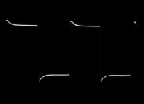
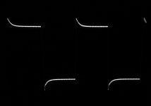
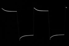
One issue with the TDA7293 is that it is quite sensitive to capacitance directly at the output. That may be speaker cable capacitance. When stabilized with the CR-string and the Zobel-network, 10nF at the output was the limit to where fine oscillations would appear. To compensate for capacitance at the output, a Thiele-network is commonly used. I used a 2.2uH choke in parallel with a 10 Ohm resistor. With that Thiele-network connected directly at the output of the TDA7293 IC and the capacitive load connected after the Thiele-network (simulating cable capacitance), the amplifier remained stable even with 1uF capacitive load.
With a square-wave signal at the input, having very fast rise- and fall-times, important overshoot at the output were observed. Though not pretty to look at, such overshoots will not be triggered by music signals as the sources are bandwidth limited not much above 20KHz.
In a quick test with a closed loop gain of -5 and 4Vpp at the output, a -3dB bandwidth in the order of 600KHz was measured. Somewhat better than for LM1875 as I recall it.
Stability tests with -5 times gain will follow.
As seen in postings #12-14, the TDA7393 starts showing fine oscillations on the output signal when the closed loop gain is set to less than 20 times (26dB), which is listed as minimum gain in the datasheet. An attempt was made to counter this oscillation. I worked on the test-board with a gain set to -3 (inverting) assuming that if I could make it work with a gain of -3, it would also work with higher levels of gain.
The TDA7293 has an input/output pin (11) to be used when more TDA7293 output stages are connected in parallel. I expected that access to this point between the preamp part and the output stage could be used in improving the stability of the amplifier with low closed-loop gains. I was wrong. The voltage signal level on pin 11 is less than 1/100th of the signal level at the output. I tried various kinds of stimulation using pin 11 but nothing gave any visible result – pin 11 seems immune to almost anything. So, work had to be on the two inputs and the output. Applying the CR-string used for the TDA7294, a Zobel-network and a Thiele-network, it was possible to stabilize the TDA7293 with a gain of -3. The principal components of the circuit are shown in the sketch (Picture 1). The further pictures show:
Tests with regulated +/-26V supply, 4 Ohm load, inverting configuration and -3 times gain.
Picture 2: 20Vpp, 1KHz, no capacitive loading of output and signal before the Thiele-network.
Picture 3: 20Vpp, 1KHz, no capacitive loading of output and signal before the Thiele-network.
Picture 4: Clipping at 46Vpp, 1KHz, no capacitive loading of output and signal before the Thiele-network.
Picture 5: 20Vpp, 20KHz, no capacitive loading of output and signal before the Thiele-network.
Picture 6: Clipping at 46Vpp, 20KHz, no capacitive loading of output and signal before the Thiele-network.
Picture 7: 20Vpp, 10KHz, 100nF capacitive loading of output and signal before the Thiele-network.
Picture 8: 20Vpp, 10KHz, 100nF capacitive loading of output and signal after the Thiele-network.
Picture 9: 20Vpp, 10KHz, 1uF capacitive loading of output and signal before the Thiele-network.
Picture 10: 20Vpp, 10KHz, 1uF capacitive loading of output and signal after the Thiele-network.
One issue with the TDA7293 is that it is quite sensitive to capacitance directly at the output. That may be speaker cable capacitance. When stabilized with the CR-string and the Zobel-network, 10nF at the output was the limit to where fine oscillations would appear. To compensate for capacitance at the output, a Thiele-network is commonly used. I used a 2.2uH choke in parallel with a 10 Ohm resistor. With that Thiele-network connected directly at the output of the TDA7293 IC and the capacitive load connected after the Thiele-network (simulating cable capacitance), the amplifier remained stable even with 1uF capacitive load.
With a square-wave signal at the input, having very fast rise- and fall-times, important overshoot at the output were observed. Though not pretty to look at, such overshoots will not be triggered by music signals as the sources are bandwidth limited not much above 20KHz.
In a quick test with a closed loop gain of -5 and 4Vpp at the output, a -3dB bandwidth in the order of 600KHz was measured. Somewhat better than for LM1875 as I recall it.
Stability tests with -5 times gain will follow.
Attachments
-
 TDA7293_10KHz_20Vpp_1uF_AfterThiele_3x.jpg171.5 KB · Views: 159
 -
 TDA7293_10KHz_20Vpp_1uF_BeforeThiele_3x.jpg183.9 KB · Views: 103
 -
 TDA7293_10KHz_20Vpp_100nF_AfterThiele_3x.jpg163.6 KB · Views: 109
 -
 TDA7293_10KHz_20Vpp_100nF_BeforeThiele_3x.jpg197.9 KB · Views: 108
 -
 TDA7293_20KHz_Clip46Vpp_NoCap_3x.jpg208.9 KB · Views: 102
 -
 TDA7293_20KHz_20Vpp_NoCapSQ_3x.jpg233.1 KB · Views: 114
 -
 TDA7293_1KHz_Clip46Vpp_NoCap_3x.jpg190 KB · Views: 103
 -
 TDA7293_1KHz_20Vpp_NoCapSQ_3x.jpg142 KB · Views: 111
 -
 TDA7293_1KHz_20Vpp_NoCap_3x.jpg176 KB · Views: 239
 -
 TDA7293Handling.jpg24.2 KB · Views: 265
TDA7293
In posting #16 the results of a stabilized TDA7293 IC, with a closed loop gain of -3, were shown.
For use of TDA7293 in a composite amplifier, a closed loop gain of -5 to -6 is more relevant. Therefore the results from posting #16 were repeated, this time with a closed loop gain of -5. It is expected that the higher the gain, the less stability problems the TDA7293 shows. And indeed, the results look quite similar to those from posting #16.
Only the gain was changed by changing the feedback resistor, the rest of the components remained as for posting #16.
Tests with regulated +/-26V supply, 4 Ohm load, inverting configuration and -5 times gain.
Picture 1: 20Vpp, 1KHz, no capacitive loading of output and signal before the Thiele-network.
Picture 2: 20Vpp, 1KHz, no capacitive loading of output and signal before the Thiele-network.
Picture 3: Clipping at 46Vpp, 1KHz, no capacitive loading of output and signal before the Thiele-network.
Picture 4: 20Vpp, 20KHz, no capacitive loading of output and signal before the Thiele-network.
Picture 5: Clipping at 46Vpp, 20KHz, no capacitive loading of output and signal before the Thiele-network.
Picture 6: 20Vpp, 10KHz, 100nF capacitive loading of output and signal before the Thiele-network.
Picture 7: 20Vpp, 10KHz, 100nF capacitive loading of output and signal after the Thiele-network.
Picture 8: 20Vpp, 10KHz, 1uF capacitive loading of output and signal before the Thiele-network.
Picture 9: 20Vpp, 10KHz, 1uF capacitive loading of output and signal after the Thiele-network.
Attachments
-
 TDA7293_10KHz_20Vpp_Gain5x_1uFBeforeThiele.jpg471.6 KB · Views: 99
 -
 TDA7293_10KHz_20Vpp_Gain5x_100nFAfterThiele.jpg218.6 KB · Views: 102
 -
 TDA7293_10KHz_20Vpp_Gain5x_100nFBeforeThiele.jpg194 KB · Views: 99
 -
 TDA7293_20KHz_Clip46Vpp_Gain5x_NoCap.jpg239.9 KB · Views: 90
 -
 TDA7293_20KHz_20Vpp_Gain5x_NoCapSQ.jpg260.4 KB · Views: 99
 -
 TDA7293_1KHz_Clip46Vpp_Gain5x_NoCap.jpg321.2 KB · Views: 95
 -
 TDA7293_1KHz_20Vpp_Gain5x_NoCapSQ.jpg298.4 KB · Views: 108
 -
 TDA7293_1KHz_20Vpp_Gain5x_NoCap.jpg225.2 KB · Views: 97
 -
 TDA7293_10KHz_20Vpp_Gain5x_1uFAfterThiele.jpg433.7 KB · Views: 108
TDA7293
As a final test of the TDA7293 IC, I found my best dual-voltage power supply in the range +/-40V to +/-50V. Unfortunately it is an unregulated power supply and while the idle voltage is +/-48V, it drops down to +/-40V at clipping of the amplifier. Anyway, it is the best I have for that purpose.
Like other analog amplifiers, the TDA7293 may change dynamic characteristics with higher supply voltage. Would my -5 times gain TDA7293 start oscillating at 40V supply? Actually it remained stable. I had to reduce the loading to 8 Ohm in order not to current-overload the TDA7293 but apart from that it did not oscillate. The output voltage margins to the supply rails remained around 3V.
In conclusion, the TDA7293 can be used down to a gain of -3 if care is taken. It has the advantages of easy paralleling without use of load balancing resistors, pretty high output power without using BTL, high bandwidth, moderate output voltage margins to the supply rails and a very attractive price (less than 3 Eur at Reichelt). As a less attractive characteristic, it seems very sensitive to capacitive loading directly at the output and a Thiele compensation network is de facto needed.
I will leave the TDA7293 for now. I also have some TDA7294/5/6 ICs but as I assume them to behave close to the TDA7293, just with less power, also those I will disregard for now.
My short-term targets are LM3886 and UTC-TDA2050V. I also have to finish my triple LM1875 BTL construction.
NB: A chip-amp used in an inverting coupling will oscillate if the input has no connection. It needs a low impedance source at the input, such as a controlling OP-AMP in a composite amplifier configuration or an input buffer.
- Home
- Amplifiers
- Chip Amps
- Chip-amps suited as power stage in a composite amplifier, LM1875/TDA2050 excluded.