raypalmer said:I've got it plugged into the bulb tester at all times until I know forsure I've got a healthy device. As for the xformer, I tested it as suggested before installing it in the box and it worked like a peach.
An externally hosted image should be here but it was not working when we last tested it.An externally hosted image should be here but it was not working when we last tested it.
I may need to use a non-cellphone camera...

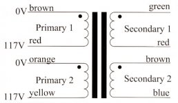
Hi Ray, I looked for the colour code of your xformer on line.
I found the diagram below and if it is correct, your primary is wired wrong. You have orange and yellow connected together and red / brown connected together??
Attachments
if the primaries are wired out of phase then the transformer alone (open circuit secondaries) will have the test bulb brightly lit.
If the primaries are in phase then the test bulb will not even glow dimly.
If the primaries are in phase then the test bulb will not even glow dimly.
Yeah, I had that same doubt so I switched the primaries a few days ago, but it lit up my bulb, at present the bulb tester is totally dark.
Hi Ray, if the diagram I posted is the same as the one on the side of your xformer, then you should connect the Brown/Orange to neutral and the Red/Yellow to Hot..
I have recently built Pedja Rogics regulated power supply for a TDA1543 DAC
and now fancy having a go at CarlosFMs regulated snubberized power supply for my LM3886 chipamp.
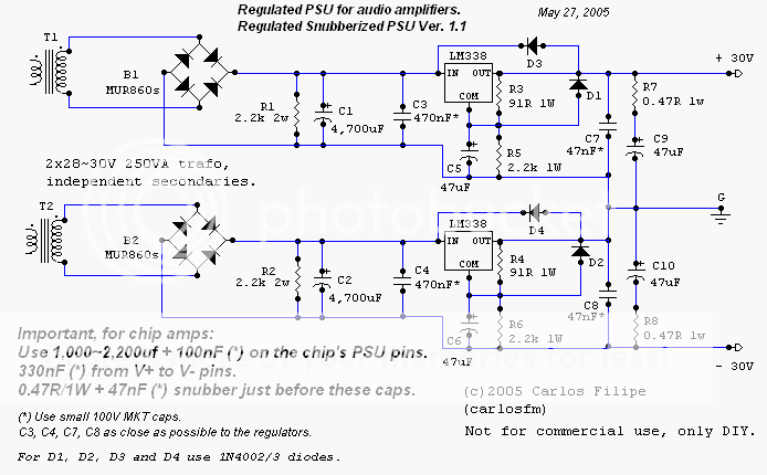
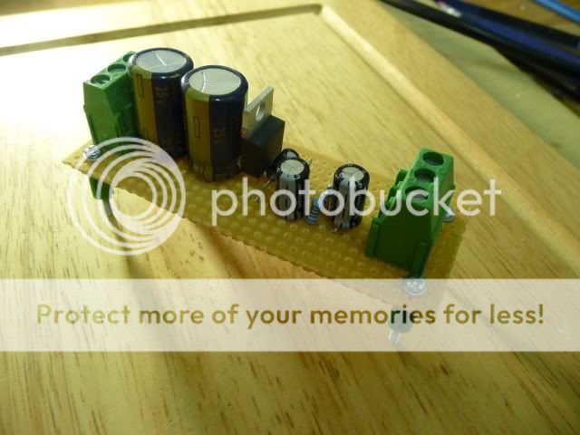
I have started to layout the components on strip board before I start to solder. I notice the schematic recommends use of MKT decoupling capacitors, would resin dipped ceramic decoupling capacitors work OK in these positions?
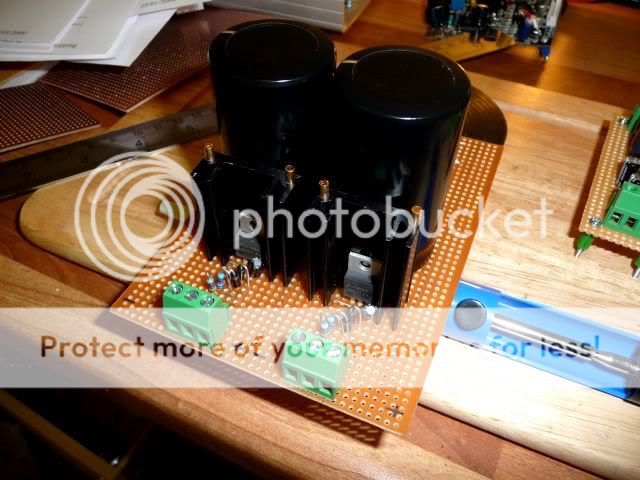
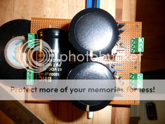
I plan to use 10000uf BHC slit foil reservoir capacitors on these boards and wondered if there was a benefit increasing the capacitance from 10000uf to say 20000uf at a later date? (I thought I might add them where the rear capacitor is lying)
N.B The voltage regulators in the photo are LM317s and these will be replaced with LM338Ts, the capacitor in the rear of the photo is purely there as a counter weight.
Thanks again Nick for putting together a great website
Richard
and now fancy having a go at CarlosFMs regulated snubberized power supply for my LM3886 chipamp.
I have started to layout the components on strip board before I start to solder. I notice the schematic recommends use of MKT decoupling capacitors, would resin dipped ceramic decoupling capacitors work OK in these positions?
I plan to use 10000uf BHC slit foil reservoir capacitors on these boards and wondered if there was a benefit increasing the capacitance from 10000uf to say 20000uf at a later date? (I thought I might add them where the rear capacitor is lying)
N.B The voltage regulators in the photo are LM317s and these will be replaced with LM338Ts, the capacitor in the rear of the photo is purely there as a counter weight.
Thanks again Nick for putting together a great website
Richard
Richard, my (clear) preference is for the Pedja Rogic discrete regulated supply for the GC! And I reckon 10,000uF is enough for a GC but as ever, I won't discourage responsible experimentation! 😉
Nuuk said:Richard, my (clear) preference is for the Pedja Rogic discrete regulated supply for the GC! And I reckon 10,000uF is enough for a GC but as ever, I won't discourage responsible experimentation! 😉
Yessss SIR! 😉
I know, but I have all of the components and I understand where these components go...I'll have a go at the discrete version later.
Do you fancy doing a nice little layout drawing of the discrete supply?
Richard
Do you fancy doing a nice little layout drawing of the discrete supply?
I do one day but I don't have the time right now. IF I can find time to take a photo of mine I will do that. It's a fairly simple circuit and shouldn't present any problems.
Alternatively, see if you can get PCB's from Pedja at Audial for his regulated PSU.
So the supply you built for your 1543 wasn't Pedja's discrete, it was based on LM317/337? 😕
Okay so I have the primaries resolved, and am getting 24v per sec.
24 x 1.4=33.6
I'm getting about 66v across the amp boards.
So... 66/2=33
It appears to be bridging the two DC supplies... why?!!?!?
24 x 1.4=33.6
I'm getting about 66v across the amp boards.
So... 66/2=33
It appears to be bridging the two DC supplies... why?!!?!?
Nuuk said:Richard, my (clear) preference is for the Pedja Rogic discrete regulated supply for the GC! And I reckon 10,000uF is enough for a GC but as ever, I won't discourage responsible experimentation! 😉
Nuuk said:
I do one day but I don't have the time right now. IF I can find time to take a photo of mine I will do that. It's a fairly simple circuit and shouldn't present any problems.
Alternatively, see if you can get PCB's from Pedja at Audial for his regulated PSU.
So the supply you built for your 1543 wasn't Pedja's discrete, it was based on LM317/337? 😕
It was based on Pedja's standard regulated ps using just a LM317.
Hi Ray,
you've got a dual polarity supply from dual secondary transformer.
Middle connection is treated as zero volts.
The other two connections from the PSU are +33Vdc and -33Vdc.
All normal for this 24Vac transformer.
you've got a dual polarity supply from dual secondary transformer.
Middle connection is treated as zero volts.
The other two connections from the PSU are +33Vdc and -33Vdc.
All normal for this 24Vac transformer.
It was based on Pedja's standard regulated ps using just a LM317.
OK, I didn't know he had done one of those! 😉
Hi Ray,raypalmer said:Okay audio1st I owe you a coke.
Now I think my secondaries are incorrect. Are they??
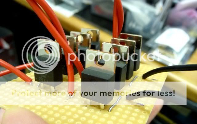
It looks as if you have 2 white wires at V- and 2 red wires at V+..
I cant see where PG- and PG+ are connected, have you just tied them together?
They need to connect to the AMP board ground..
Please let us know how you have connected these wires.
Barry..
jackinnj said:If anyone cares, I am going to have some boards burned which will approximate what National describes in application note 1849 -- only thing is that I prefer MUR860's to bridge rectifiers and a pants-n-suspenders approach to snubbers -- with TH's setup you have the provision for slow-start and mute etc. There'll also be a provision for auxiliary power for a buffer etc.:
http://www.national.com/an/AN/AN-1849.pdf
Please let us know when the board is available, and thanks for the link 🙂. Given the transformer-specific math that goes into determining snubber values, do you think the National's default values could potentially do more harm than good? Also, what do you think of the CarlosFM-like psedo-snubbers they have after the filters?
Nuuk said:
OK, I didn't know he had done one of those! 😉
You must have missed that one 😉
Nick
Did you build the first or second discrete circuit?
http://myweb.tiscali.co.uk/nuukspot/decdun/prp/supplies.htm
Did you build the first or second discrete circuit?
http://myweb.tiscali.co.uk/nuukspot/decdun/prp/supplies.htm
Tripmaster said:Nick
Did you build the first or second discrete circuit?
http://myweb.tiscali.co.uk/nuukspot/decdun/prp/supplies.htm
Both. 😉
(Technically the first isn't discrete - ie it uses the LM338 regulators.)
Nuuk said:
Both. 😉
(Technically the first isn't discrete - ie it uses the LM338 regulators.)
Sorry, you misunderstood. I was referring to schematic 2 and 3.
- Home
- Amplifiers
- Chip Amps
- Chip amp power supply- a beginners guide