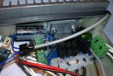
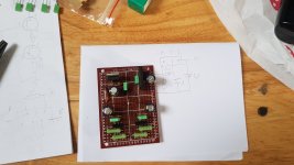
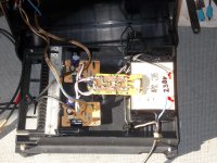
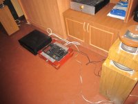
Here's my 6 channel small box amp, a four channel TDA7850 car amp chip and two TDA8932 Class D boards for the bass end. I use it with my Behringer crossover and cobbled together multiway speakers.
The TDA7850 is on a TDA7388 PCB (only a pound! Power amplifiers TDA7388 four channel 4x41W audio DC 12V BTL PC car AMP PCB JP | eBay). You can find complete TDA7850 amps on Ebay but I thought that buying a known good chip from RS components and decent caps would be a better route. I found some 1uF polypropylene input caps for a good price but they were too big really. I made 'em fit but it left no room for proper terminals for the inputs. Initially I had no terminals for the power and outputs, I soon regretted that and added them.
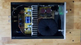
JohnAudioTech tested a completed Ebay board and found it has distortion problems, probably due to a bad layout. YouTube. The chip should do about 13W per channel into 8 ohms according to this http://www.diybudgetaudio.com/TDA7850.htm I had it on a small ATX PSU heatsink that got warm and would not fit in the box so I mounted it to this one. I can barely feel any heat at all now. It's running on a 15V switch mode laptop supply.
The TDA8932s do get warm though, even at the low 12V they're running on now. I might change those for something beefier in future. I think they can do about 20W into 8 ohm at 19V. Overall I'm pretty happy with it. I tried multiple TPA3116 boards before but had problems with hot inductors and high frequency whistles.
The TDA7850 is on a TDA7388 PCB (only a pound! Power amplifiers TDA7388 four channel 4x41W audio DC 12V BTL PC car AMP PCB JP | eBay). You can find complete TDA7850 amps on Ebay but I thought that buying a known good chip from RS components and decent caps would be a better route. I found some 1uF polypropylene input caps for a good price but they were too big really. I made 'em fit but it left no room for proper terminals for the inputs. Initially I had no terminals for the power and outputs, I soon regretted that and added them.
JohnAudioTech tested a completed Ebay board and found it has distortion problems, probably due to a bad layout. YouTube. The chip should do about 13W per channel into 8 ohms according to this http://www.diybudgetaudio.com/TDA7850.htm I had it on a small ATX PSU heatsink that got warm and would not fit in the box so I mounted it to this one. I can barely feel any heat at all now. It's running on a 15V switch mode laptop supply.
The TDA8932s do get warm though, even at the low 12V they're running on now. I might change those for something beefier in future. I think they can do about 20W into 8 ohm at 19V. Overall I'm pretty happy with it. I tried multiple TPA3116 boards before but had problems with hot inductors and high frequency whistles.
Attachments

Last edited:
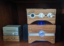
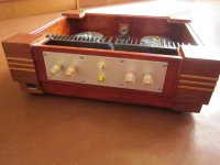
Beautifully executed - I love the bamboo boxes. I may steal your design. 😀
What volume potentiometer did you use?
Thank you! I won't press charges
ALPS RK 27 100KAx2 6mm round shaft is the potentiometer that i used.
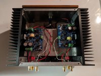
Here is my just finished Modulus 86. I used the SMPS-86 for power and some Modushop heat sinks to keep it cool. Thanks to Tom and this forum for being a resource to help me through the build. It sounds great!
Attachments
Looks good.Here is my just finished Modulus 86. I used the SMPS-86 for power and some Modushop heat sinks to keep it cool. Thanks to Tom and this forum for being a resource to help me through the build. It sounds great!

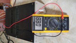
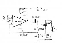
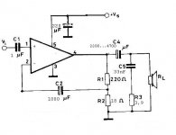
tda2002 modifikation
C1 1uF mkt,mkp
C2 1000uF 16V
output cap 2200uF 16V (or 3300uF 16V)
power supply cap 220uF 25V
R2 18 ohm
R3 3,9 ohm
C1 1uF mkt,mkp
C2 1000uF 16V
output cap 2200uF 16V (or 3300uF 16V)
power supply cap 220uF 25V
R2 18 ohm
R3 3,9 ohm
Attachments

Last edited:
tda2002 modifikation
C1 1uF mkt,mkp
C2 1000uF 16V
output cap 2200uF 16V (or 3300uF 16V)
power supply cap 220uF 25V
R2 18 ohm
R3 3,9 ohm
Hi
mjf
Why with this chip?- not with a stronger UTC like TDA2050 because the cost is just 1 euro? or is is just try out? you use the schematic of the TDA2003- but different.
What is the difference in sound?
chris
the tda2002 needs a "stiff" psu (transformer 20VA or better, electrolytic cap 10000uF or more).......with a weak psu (10VA transformer and 2200uF or sowhat) Pout shrinks to 2.....3W.
or a regulated psu, with a 15Vdc psu i got around 4,5W at 3,9ohm/1kHz.
the sound is relaxed, for long term listening.........
or a regulated psu, with a 15Vdc psu i got around 4,5W at 3,9ohm/1kHz.
the sound is relaxed, for long term listening.........
tda2002 datasheet circuit modification......(Cout not in the feedback loop):
with 2200uF cap at the output i got 20Hz (-3dB) @ 4ohm load.
upper freq. limit is around 200kHz (-3dB).
15Vdc......16Vdc unregulated power supply.
with 2200uF cap at the output i got 20Hz (-3dB) @ 4ohm load.
upper freq. limit is around 200kHz (-3dB).
15Vdc......16Vdc unregulated power supply.
Attachments

Last edited:


 English only please in future:
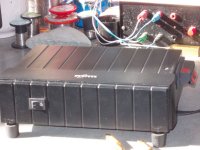
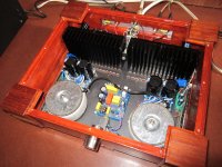
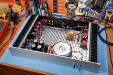
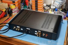
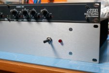
I started this build toward the end of 2018, with the aim of downsizing my previous 2.1 setup (a 2-channel Gainclone + a Samson 120a bridged for sub + a dbx 223XL crossover) to a single enclosure. I got side-tracked a lot, but with the COVID-19 lockdown & getting furloughed from my job I've finally finished it - all except finding a nice knob for the rotary power switch!
As seems to be the trend for my audio projects nothing went quite as originally planned - in particular I had multiple issues with the various KMTech boards I bought from eBay. As a result I've ended up keeping the external crossover, going with a single power supply rather than multiple & using completely different amp boards. So I know it's far from perfect, but it's a big improvement over my original 2011 build!
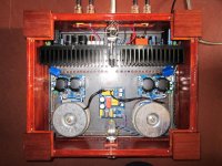
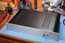
Enclosure is a 2U Dissipante from Hi-Fi2000/Modushop in Italy, audio transformer for bridging the sub amps is a Vigortronix VTX-101-007, amp boards are the open source LM3886 design from this forum's own 00940 which I had made at JLCPCB.
Many thanks to all the help I've had in various threads on the forum over the last 18 months or so!
As seems to be the trend for my audio projects nothing went quite as originally planned - in particular I had multiple issues with the various KMTech boards I bought from eBay. As a result I've ended up keeping the external crossover, going with a single power supply rather than multiple & using completely different amp boards. So I know it's far from perfect, but it's a big improvement over my original 2011 build!
Enclosure is a 2U Dissipante from Hi-Fi2000/Modushop in Italy, audio transformer for bridging the sub amps is a Vigortronix VTX-101-007, amp boards are the open source LM3886 design from this forum's own 00940 which I had made at JLCPCB.
Many thanks to all the help I've had in various threads on the forum over the last 18 months or so!
Attachments

Hello LE,
That's a very tidy build indeed, I like the perforated base in the case, that's a very good idea as well I can see from that why you bought it.
Cheers take care and happy listening
That's a very tidy build indeed, I like the perforated base in the case, that's a very good idea as well I can see from that why you bought it.
Cheers take care and happy listening
- Home
- Amplifiers
- Chip Amps
- Chip Amp Photo Gallery