An externally hosted image should be here but it was not working when we last tested it.
Just the test bed..... Zero hiss or hum fantastic sounding amps! I am just blown away. Thank you Peter Daniel! now the hard part chassis' for the blocks.
An externally hosted image should be here but it was not working when we last tested it.
I really like these! does anyone have a source for these heat sinks?
I really like these! does anyone have a source for these heat sinks?
Google "Lamina Radial Heatsink"
![IMAG0460[1].jpg](/community/data/attachments/385/385008-4e7307165700bdd871506846d303c086.jpg?hash=TnMHFlcAvd)
![IMAG0458[1].jpg](/community/data/attachments/385/385027-32386b4e576b04ab05d63d68a418105f.jpg?hash=MjhrTldrBK)
I have no idea, how one could ever read necrofilia out of stuffed😀Into necrophilia, hey ?
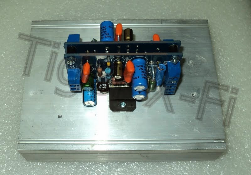
but the pcb is the same design as here: http://www.diyaudio.com/forums/chip-amps/209960-i-designed-gc-lm3875.html


thank you🙂Very cool! I really like it!
thank you🙂Nice mains filter you got there !

My LM3886 🙂


An externally hosted image should be here but it was not working when we last tested it.
An externally hosted image should be here but it was not working when we last tested it.
Those CPU heat-sinks with very close spaced fins do not allow natural convection cooling to take place. Even with the fins vertical, the heat transfer will be poor.
Frank.
Frank.
I have found even at good volume the chips generally stay cool to warm. It may not be an issue unless you play very loud into low impedance loads.Those CPU heat-sinks with very close spaced fins do not allow natural convection cooling to take place. Even with the fins vertical, the heat transfer will be poor.
Frank.
I agree with mhouston.. Unless you listen to Metallica at full tilt your heat sinks should be good.. Maybe air hole under the fins for convection cooling...
Edit: but rotate the HS so the fins face vertical...
Edit: but rotate the HS so the fins face vertical...
ARGA10W
A Really Good Amplifier 10W (?)
Got sick and tired to the noisy computer sound cards,
so I made this...


Size: H75mm (3"), W200mm (8"), D200mm (8").
Direct answer for the question "how in h...???" you will find from here:
http://www.diyaudio.com/forums/everything-else/13246-way-build-chassis-7.html#post3741821
Amplifier section simulated THD 0.0007% 1kHz/1W/8R
Reality is different because of the PCM to analog signal converted from USB port (@ max.16bit48kHz).
Expected THD around 0.006%, still need to test that though...
Anyhow:
USB DAC/ADC chip is PCM2904 by TI.
Amplifiers are LME49990 (by TI) driving CFP output stage.
Max output power to 8R is 10W and 20W to 4R.
Power supply is regulated 2x18.5V for inputstage,
and 2x16V for outputstage.
Oh, and; its "auto power on/off". Control voltage from USB.
Power light behind volume pot...
A Really Good Amplifier 10W (?)
Got sick and tired to the noisy computer sound cards,
so I made this...
Size: H75mm (3"), W200mm (8"), D200mm (8").
Direct answer for the question "how in h...???" you will find from here:
http://www.diyaudio.com/forums/everything-else/13246-way-build-chassis-7.html#post3741821
Amplifier section simulated THD 0.0007% 1kHz/1W/8R
Reality is different because of the PCM to analog signal converted from USB port (@ max.16bit48kHz).
Expected THD around 0.006%, still need to test that though...
Anyhow:
USB DAC/ADC chip is PCM2904 by TI.
Amplifiers are LME49990 (by TI) driving CFP output stage.
Max output power to 8R is 10W and 20W to 4R.
Power supply is regulated 2x18.5V for inputstage,
and 2x16V for outputstage.
Oh, and; its "auto power on/off". Control voltage from USB.
Power light behind volume pot...
- Home
- Amplifiers
- Chip Amps
- Chip Amp Photo Gallery