Engineers don't understand art. Or so I've been told.
Around here the line between artist and engineer blurs...you have to be a little of both.
Really cool amp by the way.
I said this in another forum that your project appeared in: if it was mine, I would have gone to great lengths to ensure that its reverse voltage protected, over voltage protected and input/output protected as well. I think outputs are fairly protected on modern op-amps but they don't do well with reverse polarity or over-voltage. an onboard regulator or some circuit that shuts down on 'bad things' would have been a good idea.
it looks like a LOT of work to fabricate; and powering it on by mistake the wrong way would really ruin my year (lol).
I agree to a point but this is not a mass market item it was simply a D.I.Y one off concept.
The OPAMP has quite a wide voltage range up to 36V MAX in the amps current config as its split internally (+/-18v) , not that I would want to run it at anywhere those levels.So for my own use I didn't see any point with over voltage protection
Voltage reversal has a higher chance of killing it so i suppose I should have added some protection there.
There was no point in running it from anything other than one of the many manufactured switch mode power supplies I had in the 12-24v range all of which have positive center pins I don't think I have a single PSU that is negative center to use by mistake but it could happen.
I think I used a lab power supply once to show the +/- rail voltages in the article so I guess I could have blown it up there by swopping the polarity 😱
I doubt it will even get much use as I have a lot better amps to use with my headphones.It was a fun project and saw it more of a conversation piece sat on the desk 🙂.
I am sure in this forum we all have more amps than we need or can use yet they all have a place in our minds.
an idea (too late, though): use a custom power connector and that can reduce the chances that you'll plug the wrong thing in.
anyway, I like the workmanship you put into it. I've done some air-wiring and its crushing when a part blows and you have to unbuild quite a bit to replace.
anyway, I like the workmanship you put into it. I've done some air-wiring and its crushing when a part blows and you have to unbuild quite a bit to replace.
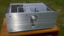
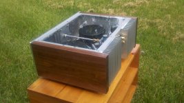
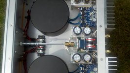
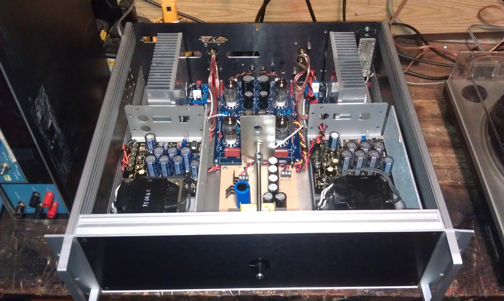
LM4780 dual mono
Audiosector LM 4780 pcbs standard BOM parallel/dual mono configuration
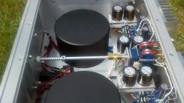
Antek an-3222 toroidal transformers with antek covers
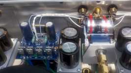
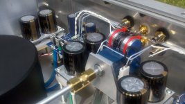
Nichicon gold tune 6800uf power supply caps, 13,600uf per rail
Clarity caps MSA 4.7uf input caps
amb e27 colume control pcb
alps rk27 potentiometer
Cardass ACBP binding posts
Cardass CTFA rca's
Schurter MSM 19LA power switch
8audio volume knob, refinished to match brushed aluminum
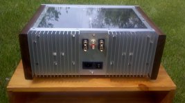
Heatsink USA 6" x 6" heatsinks
walnut side panels cut from May 8, 2009 inland hurricane storm wood, tung oil finish
2024 aluminum parts cut and finished using hand tools and a drill press
total weight @43 lbs
Audiosector LM 4780 pcbs standard BOM parallel/dual mono configuration
Antek an-3222 toroidal transformers with antek covers
Nichicon gold tune 6800uf power supply caps, 13,600uf per rail
Clarity caps MSA 4.7uf input caps
amb e27 colume control pcb
alps rk27 potentiometer
Cardass ACBP binding posts
Cardass CTFA rca's
Schurter MSM 19LA power switch
8audio volume knob, refinished to match brushed aluminum
Heatsink USA 6" x 6" heatsinks
walnut side panels cut from May 8, 2009 inland hurricane storm wood, tung oil finish
2024 aluminum parts cut and finished using hand tools and a drill press
total weight @43 lbs
Attachments
-
 1 LM4780 dual mono SoIL4x4.jpg557.3 KB · Views: 2,076
 -
 2 LM4780 dual mono SoIL4x4.jpg743.9 KB · Views: 1,984
 -
 3 LM4780 dual mono SoIL4x4.jpg523.2 KB · Views: 1,851
 -
 4 LM4780 dual mono SoIL4x4.jpg559.7 KB · Views: 1,742
 -
 5 LM4780 dual mono SoIL4x4.jpg780.5 KB · Views: 1,614
 -
 6 LM4780 dual mono SoIL4x4.jpg605.1 KB · Views: 1,029
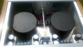
LM4780 dual mono
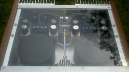
A few more.
A few more.
Attachments
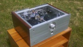
mmm hmm that sure is purdy! very clean job. Do you have anything inside to light it up so everyone can see your craftsmanship?
Gotta love functional art!
Gotta love functional art!
mmm hmm that sure is purdy! very clean job. Do you have anything inside to light it up so everyone can see your craftsmanship?
Gotta love functional art!
I could take some close ups of the interior if that is what you mean. Or if you are referring to the leds on the pcbs they are really dim. I wish they were brighter but I don't know if it is worth the trouble to swap out the resistors. They are in a tight spot.
well kinda..... i was wondering if you planned on adding "accent led lighting" on the inside since the top is acrylic..... figured it would be a neat way to show off your work.
well kinda..... i was wondering if you planned on adding "accent led lighting" on the inside since the top is acrylic..... figured it would be a neat way to show off your work.
Hmm. I don't know. That would be kind of cool, I would definatly have to change that resistor though, and maybe a different color led (they are green now). I do remember seeing on here somewhere that someone used fiber optic cable and some craft wire to make light pipes that was pretty cool, I don't know if it would look right inside my amp but it would look cool in the dark. Like looking down at a stage. Hmmmm....
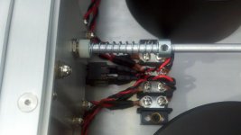
Nice work SoIL4x4. I assume the spring on the volume pot is used to adjust the resistance of the pot? Loving the clear lid, not sure how it would look if you lit the inside up.
Here is my latest amp. It's a little cMoy headphone amp built into an old iPod 40Gb case. I built it to run my new Sennheiser HD280 Pros. It runs on a single 9v battery, which can be charged via a DC jack on the bottom. The switch is for bass boost, the on/off switch is built into the volume pot. The OpAmp used is a Burr Brown OPA2132PA and I have set the gain of the system to 3.3
I used 2 SMT LEDs for the power light and charging light. These are soldered to a piece of strip board and glued to the case. In picture 2, you can see the blue LED shining through the iPod front. The charging LED is below this and is red.
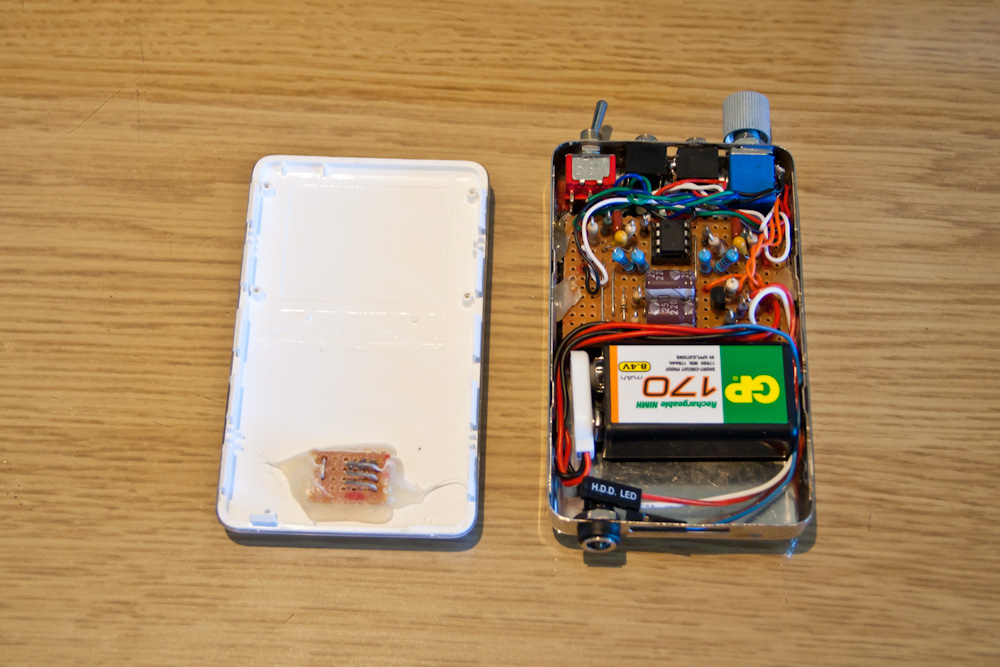
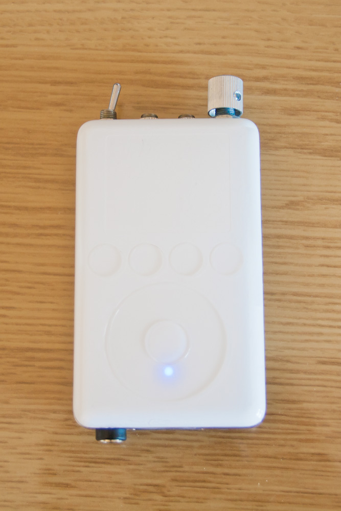
I used 2 SMT LEDs for the power light and charging light. These are soldered to a piece of strip board and glued to the case. In picture 2, you can see the blue LED shining through the iPod front. The charging LED is below this and is red.
Last edited:
Nice work SoIL4x4. I assume the spring on the volume pot is used to adjust the resistance of the pot? Loving the clear lid, not sure how it would look if you lit the inside up.
Thanks, yes there is a spring on both sides. It helps with "feel" of the knob. Yeah I may leave well enough alone on this amp and plus I ordered a lighter note today so I have to prepare for a new project😀
I love how compact your amp is. It is a great use for all the broken ipods out there!!
Last edited:
Here is my latest little amp I built of some spare parts. It runs from 12 volts and the chip used is a TDA1519C. The sound is OK, nothing compared to my Gainclone or my headphone amp, but it'll do for the workshop...
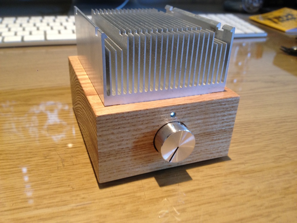
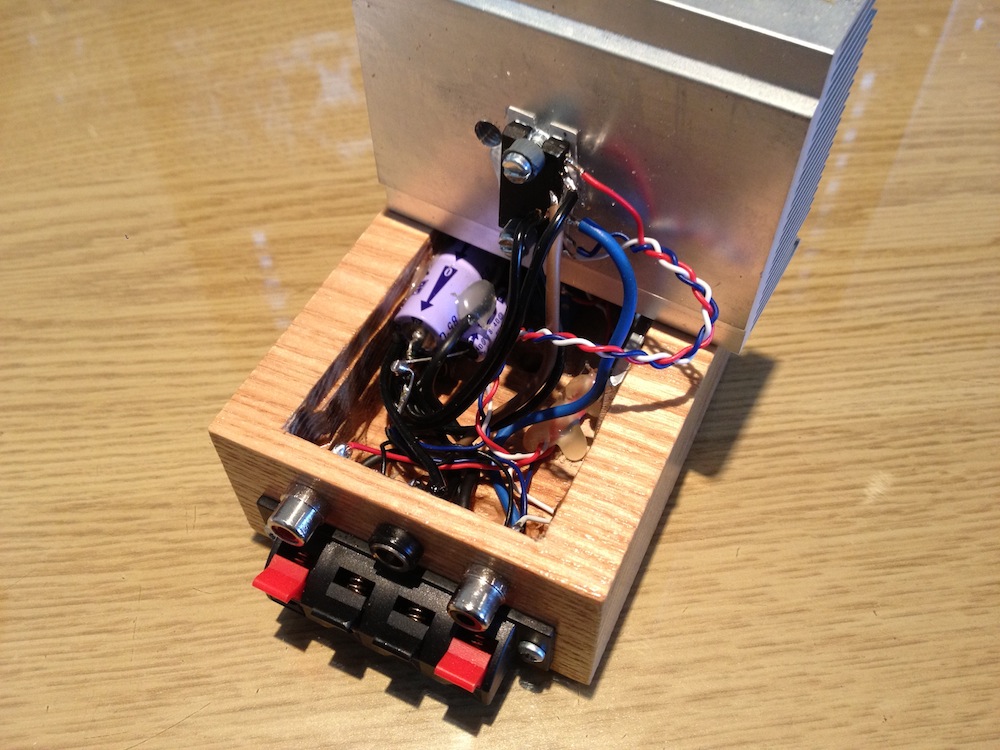
The schematic used was the one straight out of the datasheet, nothing special apart from a 10 ohm resistor between signal ground and audio ground to help with ground loops etc.
The schematic used was the one straight out of the datasheet, nothing special apart from a 10 ohm resistor between signal ground and audio ground to help with ground loops etc.
Last edited:
Audiosector LM 4780 pcbs standard BOM parallel/dual mono configuration
Antek an-3222 toroidal transformers with antek covers
Nichicon gold tune 6800uf power supply caps, 13,600uf per rail
Clarity caps MSA 4.7uf input caps
amb e27 colume control pcb
alps rk27 potentiometer
Cardass ACBP binding posts
Cardass CTFA rca's
Schurter MSM 19LA power switch
8audio volume knob, refinished to match brushed aluminum
Heatsink USA 6" x 6" heatsinks
walnut side panels cut from May 8, 2009 inland hurricane storm wood, tung oil finish
2024 aluminum parts cut and finished using hand tools and a drill press
total weight @43 lbs
love it ! --- superb 🙂
This is mine. LM3886 Ref.E diagram, plus music fidelity A1 preamp. Finished in Jan. of 2011.
An externally hosted image should be here but it was not working when we last tested it.
An externally hosted image should be here but it was not working when we last tested it.
An externally hosted image should be here but it was not working when we last tested it.
Marsvolta,
Your clean and minimal wiring really appeals to to me. Nice. Did you ever listen to the amps without a tube pre and if so what differences did you hear. Which one is that? Might be my next project - curiosity is getting the best of me.
Your clean and minimal wiring really appeals to to me. Nice. Did you ever listen to the amps without a tube pre and if so what differences did you hear. Which one is that? Might be my next project - curiosity is getting the best of me.
GC LM3886
Another my GC LM3886 :
Another my GC LM3886 :
An externally hosted image should be here but it was not working when we last tested it.
- Home
- Amplifiers
- Chip Amps
- Chip Amp Photo Gallery