
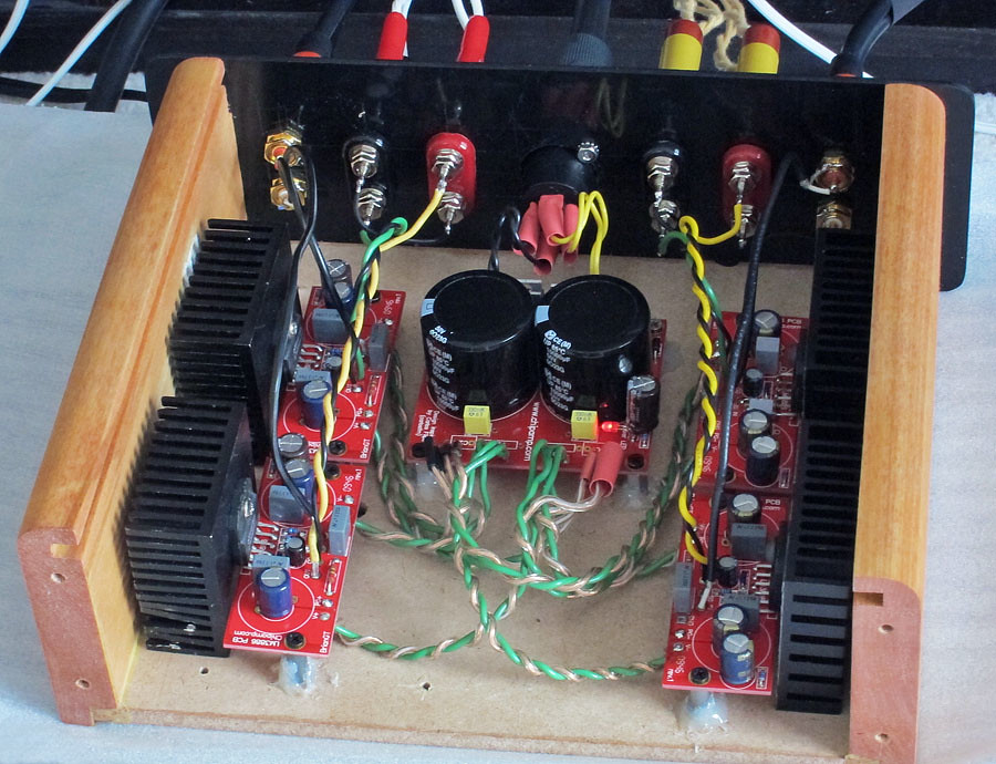
Wicked looking build. What ELNA are those at C3-C8 ? Can you tell us the components in the signal and PSU ? What brand of terminals & RCA's are those, they look nice ? Do you have pics showing the transformer and boards together ? A pic of the heatsink ?
Is there a place in the "Big" thread where I should start to read about the LF01 modules ? Has it been on yur buds FE206E : how did it sound compared to your near-field speakers ?
Is there a place in the "Big" thread where I should start to read about the LF01 modules ? Has it been on yur buds FE206E : how did it sound compared to your near-field speakers ?
Wicked looking build. What ELNA are those at C3-C8 ? Can you tell us the components in the signal and PSU ? What brand of terminals & RCA's are those, they look nice ? Do you have pics showing the transformer and boards together ? A pic of the heatsink ?
Is there a place in the "Big" thread where I should start to read about the LF01 modules ? Has it been on yur buds FE206E : how did it sound compared to your near-field speakers ?
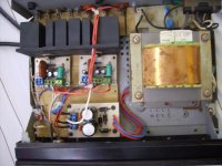
C3 and C8 are 12,000uF/63V Elna LA5 or LP5, made by Elna Thailand. They're value capacitors, but nothing special.
C13 is a generic 2.2uF axial polypropylene - again nothing special, but adequate. This is a good candidate for an upgrade.
R12 is an NOS 2k7/0.5W Allen-Bradley Carbon Composition - better choices at this location include Takman REX and Kiwame.
R13 is a generic non-magnetic 100k/0.25W/5% "Watts" CFR. Takman REX and Kiwame can also be considered here.
C12 is a 220pF/630V Wima FKP2. ERO CFR polycarbonate film/foil or a wide variety of C0Gs are usable here.
C9 is a 220uF/25V Muse KZ. Competent, but again a Black Gate is worthwhile here.
The PSU parts are: Trafo - 24-0-24, 5A EI (generic), MUR860 rectifiers and Wima MKS-3 for C5.
The terminals and RCAs come with the cabinet kit supplied by EBay seller 8Audio, who also sells them separately. They're the nicest I've touched and felt so far. The heatsink is visible on the pic with the 2 boards side-by-side. It's not very large, but adequate - I don't run it at high volumes anyway. The LF01 thread is a small thread at the Analog Line-Level sub-forum - there are some schematics, LTSpice simulations and pics there.
This setup hasn't been tested with the FE206s, only with the Jamos. It's nice sounding, but the differences aren't big, with and without the LF01 - I'll probably need a Black Gate at C9 and a better input coupling cap at C13 before the LF01 really starts standing out.
Could you ask the Moderators to move all this tech discussion to the LF Thread.
Why do we need 10 posts without any pics since post2015?
This is a pic thread.
Why do we need 10 posts without any pics since post2015?
This is a pic thread.
I hate it, hate it, hate it.
LOL ... Jealous? ...
CanAmMan: Mighty fine engineering, hope it sounds real fine as well.
LOL ... Jealous? ...
CanAmMan: Mighty fine engineering, hope it sounds real fine as well.
Thanks, Fast Eddy..... I have the chipamp in my great room, and a Pass DIY Class A F5 in a smaller listening room. Since I spend most of my casual time in the great room, the sound of the chipamp is growing on me..... It sounds excellent--but I'm not ready to give the F5 to Goodwill yet....!
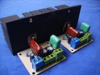
built 4 more chipamp modules for my new active crossover system. this is NOT a clean build (haha) but it does work and I may have a proper metal base plate and front/rear made.
it really is surprising how well hot-melt glue can hold and come in handy in so many ways 😉
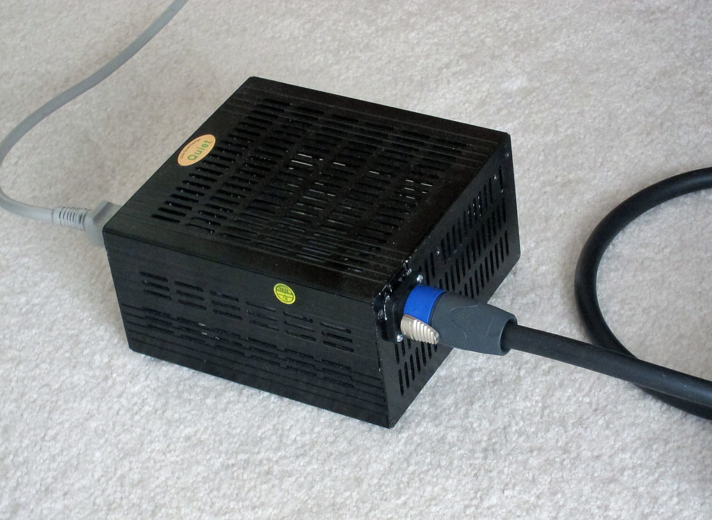
the psu is an old ATX power supply case (nice one) with a parts express toroid inside. I'm using speakon 4wire connectors and patch cables (custom made umbilical from a guy on ebay; nice timer-saver for me!)
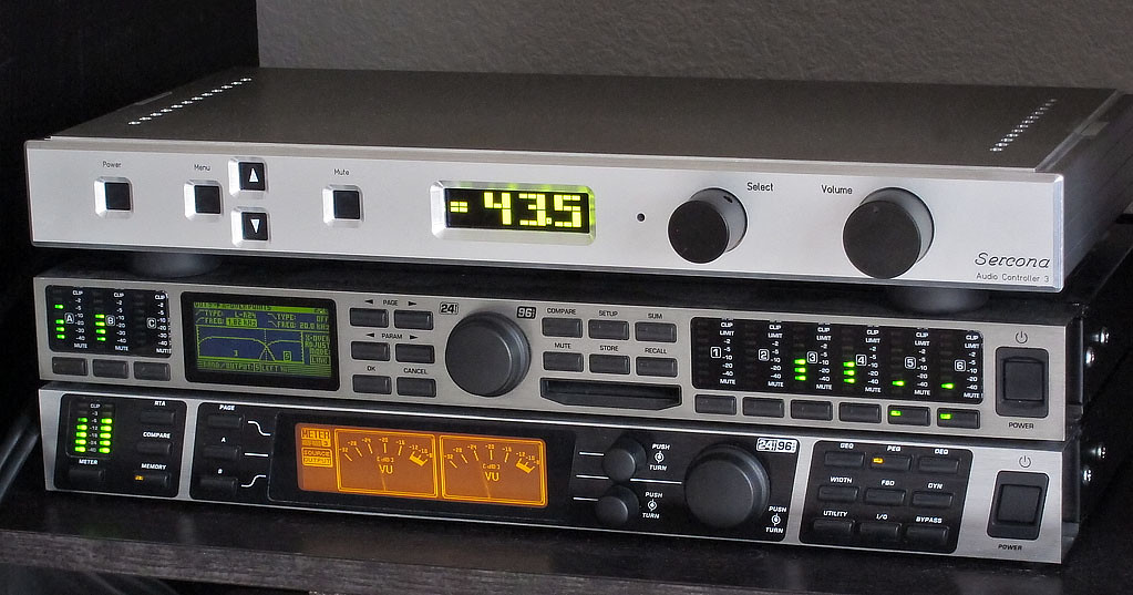
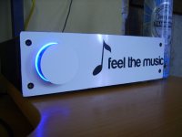
the 'fun part' is the configuration side. here I am using the behringer twins (lol) for active XO and some EQ. the box on top is my own build and design and its a 6ch volume control/selector (and spdif switch, too).
I have brand new speakers, too! just built these last week from madisound cabinets (simply love these!) and the zaph audio L18 driver set (seas drivers):

there is nothing between the drivers and chip-amp. I thought about using a blocking safety cap for the tweeter but so far its still a straight wire inside. not even a passive XO inside, I opted to make this an active system from the very start.
of note to the chip-amp stuff, I'm not getting any hum. I was told that driving 4 modules from a single PSU like that would be trouble but so far, I don't hear any problems. and with the trafo very remoted; there's no trafo hum at all.
it really is surprising how well hot-melt glue can hold and come in handy in so many ways 😉
the psu is an old ATX power supply case (nice one) with a parts express toroid inside. I'm using speakon 4wire connectors and patch cables (custom made umbilical from a guy on ebay; nice timer-saver for me!)
the 'fun part' is the configuration side. here I am using the behringer twins (lol) for active XO and some EQ. the box on top is my own build and design and its a 6ch volume control/selector (and spdif switch, too).
I have brand new speakers, too! just built these last week from madisound cabinets (simply love these!) and the zaph audio L18 driver set (seas drivers):
there is nothing between the drivers and chip-amp. I thought about using a blocking safety cap for the tweeter but so far its still a straight wire inside. not even a passive XO inside, I opted to make this an active system from the very start.
of note to the chip-amp stuff, I'm not getting any hum. I was told that driving 4 modules from a single PSU like that would be trouble but so far, I don't hear any problems. and with the trafo very remoted; there's no trafo hum at all.
Is there any thread describing the top preamplifier you made? I'd love to see it in underwear 🙂
I would have opted for some taller smoothing capacitors, but it should be enought for sure.
I would have opted for some taller smoothing capacitors, but it should be enought for sure.
the internals to the preamp are still 'under construction'. its currently a set of 3 PGA 12v-version chips, an LCDuino controller and external i2c for spdif-switch control. when the proto is worked out to my satisfaction, I'll do a run of boards and do a group-buy; but I don't have a date for that yet.
Please take a look at an integrated build thread based on the MyRef-C amp.
http://www.diyaudio.com/forums/chip-amps/203666-myref-integrated-solutions-2.html#post2851953
http://www.diyaudio.com/forums/chip-amps/203666-myref-integrated-solutions-2.html#post2851953
My TDA7294 AMP
Hello all.
I'm just finished my chipamp, based TDA7294 datasheet provided circuit.
Pls have a look.
All circuit are made new except chassis and heatsink are salvaged from junkyard. Any comments are welcomed..
Check-it-out..
Hello all.
I'm just finished my chipamp, based TDA7294 datasheet provided circuit.
Pls have a look.
An externally hosted image should be here but it was not working when we last tested it.
All circuit are made new except chassis and heatsink are salvaged from junkyard. Any comments are welcomed..
Check-it-out..
The photo is dead in the thread but you can see the photos by clicking the question mark...
It looks very nice!!
It looks very nice!!


Nice looking amp! What's the thickness of the aluminum?
thickness of the all aluminum panel 4 mm. CNC milling.
Beech sockets on the sides.
Last edited:
First project - Chip Amp
Hi all,
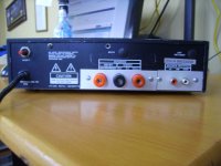
See below my first project.
I didn't start to complicated with this small chip amp which comes in a kit .
But there was a lot to learn and I really enjoyed it.
The casing is from recycled bits which creates a rustic look.


please comment on the casing, hard wiring and arrangement...I'm keen to learn.
Bastien
Hi all,
See below my first project.
I didn't start to complicated with this small chip amp which comes in a kit .
But there was a lot to learn and I really enjoyed it.
The casing is from recycled bits which creates a rustic look.
please comment on the casing, hard wiring and arrangement...I'm keen to learn.
Bastien
Last edited:
bdos: that rca cable line-in goes RIGHT NEXT to the trafo!
that has to be causing hum. it has to be. I would not route it that way if I were you.
that has to be causing hum. it has to be. I would not route it that way if I were you.
- Home
- Amplifiers
- Chip Amps
- Chip Amp Photo Gallery