Hi palstanturhin,
Great looking amps. Please can you tell me how they are assembled. I assume the amp in the first pic has threaded inserts in the wood to allow the front panel the be attatched, but how is the second one assembled?
Great looking amps. Please can you tell me how they are assembled. I assume the amp in the first pic has threaded inserts in the wood to allow the front panel the be attatched, but how is the second one assembled?
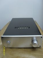
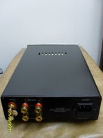
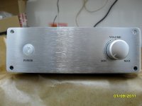
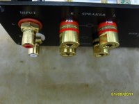
portreathbeach got it right with the first set. The wood used in these is oak, very hard, easily threaded...Second amp has an alu frame made of different alu-profiles, like L,I,C, and even O!The heatsinks are first attached to similar length L-profiles. L-profiles also on the front and back... To these are attached the front and back plates 60mm wide 4mm thick alu... and the wooden sides.Bottom plate is 1mm alu sheet, and fastened with small L-profiles again to the 'main frame'...Back plate stays on with the binding posts and what ever connectors, front plate with the potentiometer and the toggle switch.Size is: W20cm(8"), H6cm(2.4"), D25cm(10")...No shots inside unfortunately...
My recently finished tube buffered gainclone
Attachments
-
 SDC11165.jpg428 KB · Views: 2,156
 -
 SDC11169.jpg450 KB · Views: 2,044
 -
 SDC11138.jpg493.4 KB · Views: 1,912
 -
 SDC11159.jpg445.4 KB · Views: 1,790
 -
 SDC11161.jpg480 KB · Views: 1,687
 -
 SDC11144.jpg483.3 KB · Views: 885
 -
 SDC11153.jpg562.1 KB · Views: 1,073
 -
 SDC11151.jpg531.5 KB · Views: 930
 -
 SDC11142.jpg523.5 KB · Views: 763
Sound clean and soft, maybe not so powerful like PA100 and PA150 but more detailed.another very clean and good work. How its sounds with tube buffer ?
Professor,
Very, very nice construction. I was attracted to your use of one transformer for multiple voltages. I am working on a build that requires four -Amp x 2, DAC, Pre and Lighter Note. I may use discrete transformers for the amps but would still like to combine the rest on one toroid if possible.
Can you point me to a source where I can get the information I need? I'm assuming you did a DIY board of some type.
Also, what's the flavor of the white wire?
Thanks
Last edited:
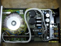
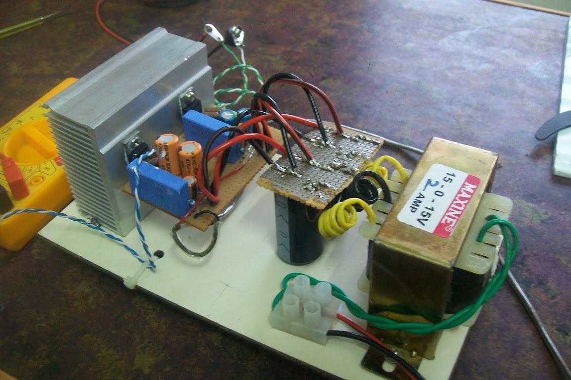
I buy 2x25V toroid and wind missing windings myself. Originally I reel up some turns and I define how many it is necessary turns on one volt. Further I multiply the received number of turns on necessary voltage. For examlpe, you have received 5 turns on 1 volt, you need 25 volts, then you need 5*25=125 turns.Professor,
Very, very nice construction. I was attracted to your use of one transformer for multiple voltages. I am working on a build that requires four -Amp x 2, DAC, Pre and Lighter Note. I may use discrete transformers for the amps but would still like to combine the rest on one toroid if possible.
Can you point me to a source where I can get the information I need? I'm assuming you did a DIY board of some type.
Also, what's the flavor of the white wire?
Thanks
White wire is copper covered with silver in teflon.
Professor - Now that's what I call DIY - Impressive!
If you don't mind, what is the green board under the transformer?
If you don't mind, what is the green board under the transformer?
Green board is FR4, became green after etching in ammonium persulfate, i dont know why =)Professor - Now that's what I call DIY - Impressive!
If you don't mind, what is the green board under the transformer?
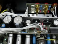
Chipamp just lift off from the kitchen table:


OPA 549, 2x 100VA trafo ; +-25V DC; 22 000uf per rail. Non Inverting config, thanks forum member Alcaid for PCB layout.
Enclosure aluminium top cover still need polishing and M6 100mm screws (ordered).
In addition to the wooden enclosure came eight meat boards 😀
Sounds nice, no hum - i will compare it with my LM3875 NI and take some measurements with scope and sound-card tomorrow.
Tnx,
I do risky - I do not use any speaker protection - my speakers are not so expensive and I'm not loud music and high-power fan.
I do risky - I do not use any speaker protection - my speakers are not so expensive and I'm not loud music and high-power fan.
LM4780 based 5.1 system
Hi guys, just finished my long pending 5.1 amplifier system


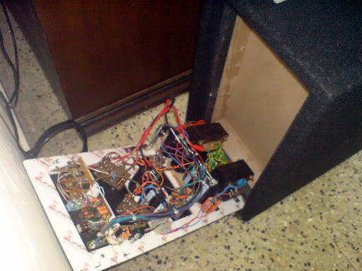

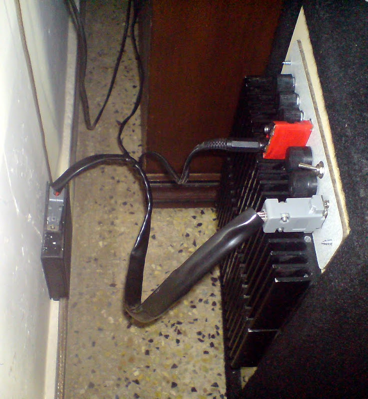
link to album - LM4780 based 5.1 system
and my lm1875 amplifier
link - LM1875 amplifier
Hi guys, just finished my long pending 5.1 amplifier system
link to album - LM4780 based 5.1 system
and my lm1875 amplifier
An externally hosted image should be here but it was not working when we last tested it.
link - LM1875 amplifier
BPA150 Working
To avoid double posting, here is a link to the story of my struggle with a BPA-150 build
http://www.diyaudio.com/forums/group-buys/137430-bpa300-round-2-a-113.html#post2705789
To avoid double posting, here is a link to the story of my struggle with a BPA-150 build
http://www.diyaudio.com/forums/group-buys/137430-bpa300-round-2-a-113.html#post2705789
Work-in-progress on the first of my two LM3886 monoblocks. I thought I'd need a drill-press/pillar-drill for the aluminium but discovered it was actually easy enough to do by hand with my old power dill. Just waiting for some adhesive pads to arrive in the post so I can mount the tank caps. I think I wired up the MUR860's right, but I'm going to check before I go any further.
Before anybody pulls me up on it, yes I know the dangers of 240VAC, I'm probably going to add a mesh lid/sides once I've got them both working. I'm completing this one & seeing how well it works before I start on the second.
An externally hosted image should be here but it was not working when we last tested it.
An externally hosted image should be here but it was not working when we last tested it.
An externally hosted image should be here but it was not working when we last tested it.
An externally hosted image should be here but it was not working when we last tested it.
Before anybody pulls me up on it, yes I know the dangers of 240VAC, I'm probably going to add a mesh lid/sides once I've got them both working. I'm completing this one & seeing how well it works before I start on the second.
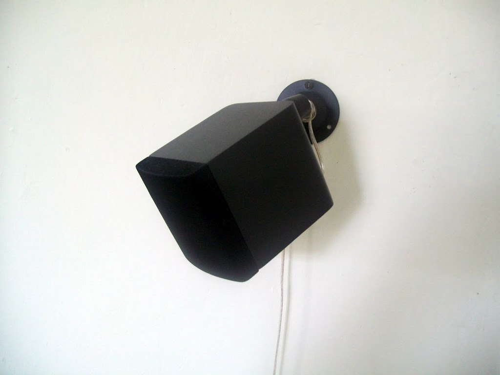
@Kuldeep Singh Ji, great work. I have been working on developing a 5.1 channel amplifier for the last few years and still not complete. Your work is very inspiring. Well planned layout. Is the VGA connector the inputs ? where are they coming from on the device mounted to the wall?
- Home
- Amplifiers
- Chip Amps
- Chip Amp Photo Gallery