That is my own designed and made case. Made out of 5mm thick alluminium, with heatsinks as the side walls.
" ... Bass could be better though, just trying to fix that now. ..."
Maybe add more PS filter capacitance?? This sometimes will put some "guts" into the bass.
Fixes for the high end, like fast recovery diodes in the bridge(s) and larger poly snubbing caps in parallel with the PS filter electrolytics also may improve the bass as well ...
That chassis is classy ... 😉
Maybe add more PS filter capacitance?? This sometimes will put some "guts" into the bass.
Fixes for the high end, like fast recovery diodes in the bridge(s) and larger poly snubbing caps in parallel with the PS filter electrolytics also may improve the bass as well ...
That chassis is classy ... 😉
Yes i am planning on adding more PS capacitance, at the moment i have 4x 10,000uF in the amp. 10,000 on each supply rail, i will double this soon. Fast diodes will be the next upgrade, or perhaps just 4 snubber caps accross the bridge rectifiers. I have 1uf accross the chips supply rails, might be better to have 0.1uF as well.
It has also been pointed out to me that my high pass filter may be set to high.
See the thread on my design.
It has also been pointed out to me that my high pass filter may be set to high.
See the thread on my design.
I see two chips per side. Since I don't see an inverting circuit / phase splitter I would "assume" they were parallel.
If so you may need a buffer to drive both chips adequately. I see you're using a passive pre, LOTS of people recommend a buffer. I am currently using an electronic high pass as the buffer in front of my LM38xx chips. I could tell a night and day difference in the "robustness" of the chip when I went from straight passive pot to the electronic xo between. High pass xo is set @ 50 Hz so it is probably not a "less load" type situation...
If so you may need a buffer to drive both chips adequately. I see you're using a passive pre, LOTS of people recommend a buffer. I am currently using an electronic high pass as the buffer in front of my LM38xx chips. I could tell a night and day difference in the "robustness" of the chip when I went from straight passive pot to the electronic xo between. High pass xo is set @ 50 Hz so it is probably not a "less load" type situation...
Reboxed my cmoy, as I had it in a dodgy plastic box with external battery pack.
Now nice and tidy with 2x9v batteries inside. All I need to do now is find 2 of those quick release 9v battery holders to mount in the back, but this'll do for travel next week to NZ.
I'm still amazed at the great sound you get out of these things. burbrown 132's (or 134? can't remember now)...
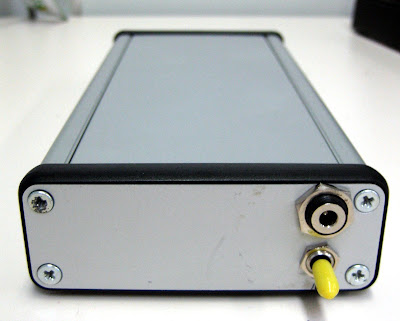
anyway pretty self explanatory front in/out low/high impedance headphones, vol. Back is power switch battery/off/external.
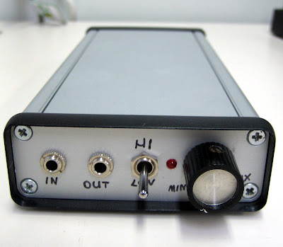
Never noticed the screws look a bit messy, but thats how I got the box still in sealed plastic, but screws look dodgy.
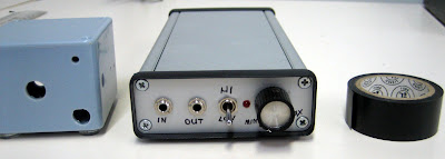
Old box I used, new cmoy case, roll of std electrical tape for size comparison.
 /></a>
Now nice and tidy with 2x9v batteries inside. All I need to do now is find 2 of those quick release 9v battery holders to mount in the back, but this'll do for travel next week to NZ.
I'm still amazed at the great sound you get out of these things. burbrown 132's (or 134? can't remember now)...
anyway pretty self explanatory front in/out low/high impedance headphones, vol. Back is power switch battery/off/external.
Never noticed the screws look a bit messy, but thats how I got the box still in sealed plastic, but screws look dodgy.
Old box I used, new cmoy case, roll of std electrical tape for size comparison.
/></a>amazing how your ears adjust to what you've got.
After thinking my pda was ok as is, I plugged the cmoy in and the sound is so much 'fuller' deeper bass (not louder, but more guts). Removed the amp and sounded like listening through a 2 meter pvc pipe :-/, tried adjusting the mixer and volume, but just can't get that 'sound', for $30 worth of parts makes any headphone 'better' 🙂 hehehe.
After thinking my pda was ok as is, I plugged the cmoy in and the sound is so much 'fuller' deeper bass (not louder, but more guts). Removed the amp and sounded like listening through a 2 meter pvc pipe :-/, tried adjusting the mixer and volume, but just can't get that 'sound', for $30 worth of parts makes any headphone 'better' 🙂 hehehe.

Poseidons Voice Anjali Amplifier
Well, she's finally come to life!
Front
Rear
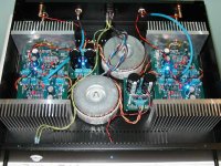
Guts
400VA/22X2 Plitron transformers per channel. Lundahl 1676 input amorphous core trannies, wired so I get either 30dB or 24dB of gain, and many other goodies. For more info and pics look here
Best,
Anand. 😉
Well, she's finally come to life!
Front
An externally hosted image should be here but it was not working when we last tested it.
An externally hosted image should be here but it was not working when we last tested it.
Rear
An externally hosted image should be here but it was not working when we last tested it.
An externally hosted image should be here but it was not working when we last tested it.
Guts
An externally hosted image should be here but it was not working when we last tested it.
400VA/22X2 Plitron transformers per channel. Lundahl 1676 input amorphous core trannies, wired so I get either 30dB or 24dB of gain, and many other goodies. For more info and pics look here
Best,
Anand. 😉
Anand,
AudioCircle is replacing your pics with a banner... you will either need to attach the pics to the forum database i(or hope people follow the link)
dave
AudioCircle is replacing your pics with a banner... you will either need to attach the pics to the forum database i(or hope people follow the link)
dave
Anand,
Looks good! How does it sound/perform with the Lundahl input trannies vs. without? I'm very curious as to what the trannies add to the mix.
Best,
KT
Looks good! How does it sound/perform with the Lundahl input trannies vs. without? I'm very curious as to what the trannies add to the mix.
Best,
KT
KT,
Thanks. Lundahl amorphous core trannies in fact, add a little depth, are slightly more extended on the top end (without getting edgy) and give the low end a little "kick." They are pretty sonically transparent, and I definitely do prefer them in. I've had them set for 1:1 or 2:1, which gives me the full 30dB gain or steps it down to 24 dB gain. Galvanic isolation is just icing on the cake. The sound emanates from a spooky black background.
I first saw this used in Art Audio's Lissa. Thanks to Kevin Carter for helping out with this one.
Dave (planet10),
Thanks for the heads up. The pics show up fine for me, even on a different computer/server. I hope people just follow the link!
Best,
Anand.
Gainclone Pointzero Kit Bridge 100W/CH
This is my second DIY Gainclone amp which run in bridge configuration, I bought the PCB boards only from Aaron who owns the EZamps website and I used Vishay/Dale metal film resistors, WIMA coupling caps, Panasonic FC electrolytic caps, OPA2134 OP Amp, OP07 OP Amp for servo. Dual Avel 160VA 22v transformer. I built a 50watt version of this kit but now prefer the 100 watt amp a lot of power. Listening impressions is very good even though this amp is not break in yet the details, imaging and clarity of this amp is amazing.
Jerry
Attachments
Extremely Well Done
That even impresses me. Thank you for taking the time to build this amplifier the way you wanted it. You've taken the basic kit, which is good by itself, and made it fit for royalty.
Very well done, sir! 😎
That even impresses me. Thank you for taking the time to build this amplifier the way you wanted it. You've taken the basic kit, which is good by itself, and made it fit for royalty.
Very well done, sir! 😎
nycavsr2000 said:The pics show up fine for me, even on a different computer/server. I hope people just follow the link!
The pictures would be coming out of your browser's local cache.
dave
Ok, as already mentioned in my thread about the CSS FR125S in aperiodic box, I build an accompanying amplifier for them from briangt lm3886 set.
I challenge everyone to build all 3 PCB's + toroid in a smaller package:....  I had a lot of fun (and stress ) trying to make the whole thing fit like that, there is really no inch left unused....
Contrary to what you would expect there is no humming/noise audible at all...
I did not really know what to expect from these, but I was pleasantly surprised, this small amp really plays on the same level (or higher) as the big Marantz below it.
Cooling is on the minimalist side, the heatsink gets about 50 degrees celcius. But considering the case of the amp below it already gets 50 degrees when used the whole day I don't consider this a problem...
The power led isn't visible when off, because the hole isn't drilled completely through the front panel. Gives a cool effect in real life, the photo's don't do it justice..
I challenge everyone to build all 3 PCB's + toroid in a smaller package:....
I had a lot of fun (and stress ) trying to make the whole thing fit like that, there is really no inch left unused....An externally hosted image should be here but it was not working when we last tested it.
An externally hosted image should be here but it was not working when we last tested it.
An externally hosted image should be here but it was not working when we last tested it.
Contrary to what you would expect there is no humming/noise audible at all...
I did not really know what to expect from these, but I was pleasantly surprised, this small amp really plays on the same level (or higher) as the big Marantz below it.
Cooling is on the minimalist side, the heatsink gets about 50 degrees celcius. But considering the case of the amp below it already gets 50 degrees when used the whole day I don't consider this a problem...
The power led isn't visible when off, because the hole isn't drilled completely through the front panel. Gives a cool effect in real life, the photo's don't do it justice..
"The power led isn't visible when off, because the hole isn't drilled completely through the front panel."
Is it Plexi or Lexan or something? It does look good.
Is the pwr switch upside down?
Is it Plexi or Lexan or something? It does look good.
Is the pwr switch upside down?
troystg said:"The power led isn't visible when off, because the hole isn't drilled completely through the front panel."
Is it Plexi or Lexan or something? It does look good.
Is the pwr switch upside down?
It is white plexi (acryl), I bought from an industrial plastic's warehouse nearby. It wasn't my initial intention to use this particular plastic, I have a laptop standard made of some VERY nice plastic. It has a soft feeling to it on top, and a whitish matte finish, but still kind of transparent. But at the warehouse they didn't know what it was so I had to settle for this stuff. Turned out rather nice, but I would have preferred the other material. I suspect that that is some normal transparent plexi, with some special surface treatment, something with steel whool maybe.
About the power switch: HAHA 😀 , so I did turn it the wrong way up after all, I tried to figure out what the normal way is, but looking at pictures from the Internet I couldn't figure it out...😕
Speedsmile said:
About the power switch: HAHA 😀 , so I did turn it the wrong way up after all, I tried to figure out what the normal way is, but looking at pictures from the Internet I couldn't figure it out...😕
Don't get too stressed. If you were living in this part of the world, the way you have fitted it is the correct way. It depends where you live as to whether OFF should up or down. Seriously.
For a power switch position, there may be regional standards, but I install a power switch considering the easy way for the preferred condition and also decided by the safe position. Pushing up is difficult.
On the MIL spec oscilloscope TEK 465M, the power switch had to be pulled out for ON position
Gajanan phadte
On the MIL spec oscilloscope TEK 465M, the power switch had to be pulled out for ON position
Gajanan phadte
- Home
- Amplifiers
- Chip Amps
- Chip Amp Photo Gallery