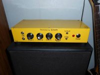
LM3875 Guitar Amplifier
Got this built after taking a long time to design the preamplifier and getting the chipamp section to work flawless.
Lots of hours spent trying to get just the right sound out of the fender tone stack circuit and testing various speakers.
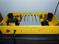
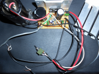
Uses LM3875 at 35 volts 1amp in single supply mode.
Has a 8200uF cap on the power supply, and a 4700uF for the output capacitor. Optional components were added as specified in the TI datasheet since it helped greatly reduce any chance of circuit feedback considering the sensitivity of the preamp.
Preamplifier is designed around two 2N5551 transistors having plenty enough gain to almost bring the chipamp to input clipping using the input set to clean. Clipping should not be an issue with normal guitar playing.
When overdrive is toggled it puts two "fuzz" diodes into the second transistor output and increases the first transistor stages gain, keeping the overdrive/clean at the same volume levels.
Power on/off is also the volume control. When turned on at full volume even with overdrive turned on there is absolutely no hum. Tiny bit of white noise from preamp transistors, but no more than any other guitar amp at full blast with no input.
Sure it could use more power but it is plenty loud to shake pictures off the wall and get noise complaints and enough for a practice amp or playing along with some other people 😀
Don't ask me about the names of the controls or where I came up with "Yellow Crush" lol.
I may post the schematic in the future but I have to draw it in software first.
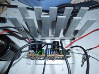
I want to thank everyone who helped me with the grounding help. I took all the advice and feel that I did a pro job under the hood.
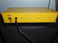
Most all of it was built out of scrap parts, hence the not so professional looking chassis.
More: DIY LM3875 Guitar Amplifier - My Photo Gallery
Got this built after taking a long time to design the preamplifier and getting the chipamp section to work flawless.
Lots of hours spent trying to get just the right sound out of the fender tone stack circuit and testing various speakers.
Uses LM3875 at 35 volts 1amp in single supply mode.
Has a 8200uF cap on the power supply, and a 4700uF for the output capacitor. Optional components were added as specified in the TI datasheet since it helped greatly reduce any chance of circuit feedback considering the sensitivity of the preamp.
Preamplifier is designed around two 2N5551 transistors having plenty enough gain to almost bring the chipamp to input clipping using the input set to clean. Clipping should not be an issue with normal guitar playing.
When overdrive is toggled it puts two "fuzz" diodes into the second transistor output and increases the first transistor stages gain, keeping the overdrive/clean at the same volume levels.
Power on/off is also the volume control. When turned on at full volume even with overdrive turned on there is absolutely no hum. Tiny bit of white noise from preamp transistors, but no more than any other guitar amp at full blast with no input.
Sure it could use more power but it is plenty loud to shake pictures off the wall and get noise complaints and enough for a practice amp or playing along with some other people 😀
Don't ask me about the names of the controls or where I came up with "Yellow Crush" lol.
I may post the schematic in the future but I have to draw it in software first.
I want to thank everyone who helped me with the grounding help. I took all the advice and feel that I did a pro job under the hood.
Most all of it was built out of scrap parts, hence the not so professional looking chassis.
More: DIY LM3875 Guitar Amplifier - My Photo Gallery
Attachments

Last edited:
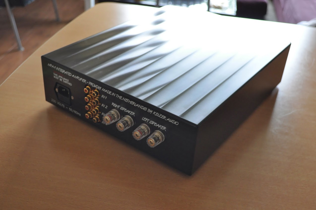
Aluminum amplifier: THE END!
Finally finished my amplifier this weekend.
Here are the results:


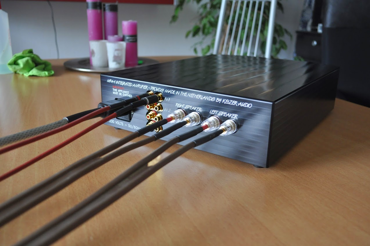

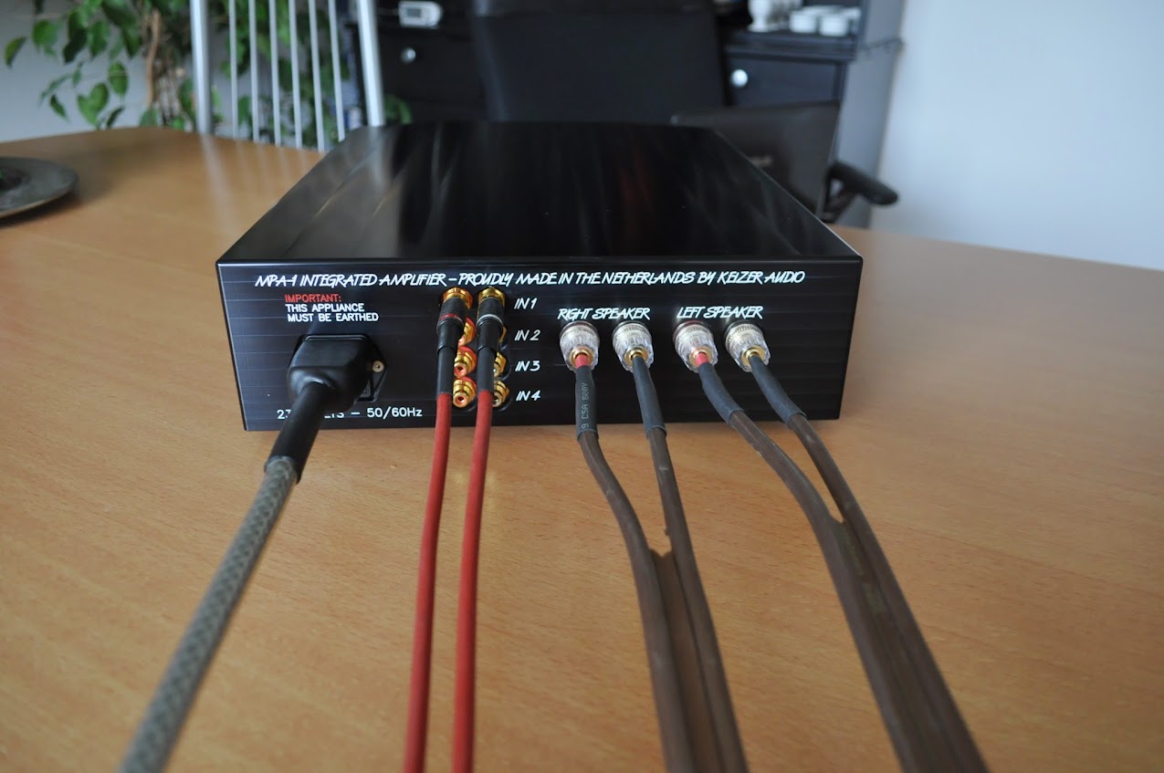

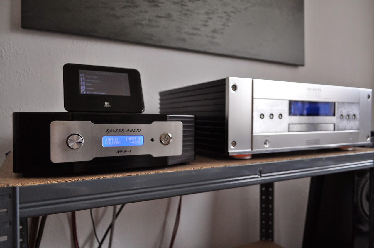

In good company:
Finally finished my amplifier this weekend.
Here are the results:
In good company:
An externally hosted image should be here but it was not working when we last tested it.
Beautiful on the outside.. How's the inside?
There are some pictures of that on my thread. I didn't took any this weekend because i was so eager to listen again.
I'll be able to make some later on 😉
BTW I don't have enough time to search through this whole thread but is my guitar amp the first one presented here using a chipamp?
If so it is cool knowing I am the first to show pics of the LM3875 being used for something other than HIFI amps.
No comments from anyone yet, it must be fugly lol 😛
If so it is cool knowing I am the first to show pics of the LM3875 being used for something other than HIFI amps.
No comments from anyone yet, it must be fugly lol 😛
Last edited:
On the contrary I think the guitar amp is awesome... I was waiting for you to post the schematic as you mentioned you might... I may do something similar with parallel lm3886's for a friend.
I will get around to drawing it up ASAP. I will probably make a thread just for that alone, and if you want I will keep your username in mind and send you it.On the contrary I think the guitar amp is awesome... I was waiting for you to post the schematic as you mentioned you might... I may do something similar with parallel lm3886's for a friend.
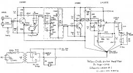
Yellow Crush Guitar Amp Schematic
For those who were curious about the schematic to my LM3875 guitar amp shown above in this thread, well here it is..
Hand drawn using an old engineering stencil but it should be legible. Too lazy to make the schematic in software yet.
I do not believe there are any errors in the schematic.
You will notice a few oddities with part values on the LM3886 but I simply used parts that were as close as I could get to what the datasheet suggested and it works perfectly fine.
The 1uF capacitor on the negative side of the chips positive input bias seems to be necessary when using it in single supply mode. I received this advice from a few other people and it does help reduce turn on thump and any bias hum without any detrimental effects.
Cable to the Clean/Fuzz toggle switch and cables to the tone stack should be shielded and grounded as shown for best results and to reduce any ground hum/loops.
Please give credit where due. It took me a long time to model the right values for the tone stack and design the preamp just right from scratch 🙂
Attachments
Last edited:
Wow! Great contribution! Are the feedback resistors really megohm multiples? (Edit: zoomed in full and see its "k" not "m"). Im trying to get a lead guitarist buddy of mine into DIY. Im glad you posted this. Maybe we'll try it out.
Thanks darklife
Thanks darklife
Last edited:
Whats the reason for a 1k in series with 2200uf from pin 1 to ground?
I think I get it. I was expecting to see power supply caps there but youre showing them bottom left. So the 1k just limits current and creates filter with 2200uf for the preamp supply.
I think I get it. I was expecting to see power supply caps there but youre showing them bottom left. So the 1k just limits current and creates filter with 2200uf for the preamp supply.
Last edited:
Exactly.So the 1k just limits current and creates filter with 2200uf for the preamp supply.
The only resistors that are in the megaohms are the ones for each transistor going from its base to the preamp positive rail which is 2.2Mohm and there are only two total.Are the feedback resistors really megohm multiples?
Any further questions should probably be in PMs so not to derail the purpose of the thread, but thanks for the input 🙂
BTW in my last post I meant "LM3875", no idea why I said 3886 lol. For some reason the edit button is missing.
Last edited:


Member
Joined 2009
Paid Member
LM3875 low power
Hi,
New amp in my family of LM's, a LM3875 low power, pcb's from Chipamp :
Build thread :
http://www.diyaudio.com/forums/chip-amps/271984-lm3875-chipamp.html
Phil.
Hi,
New amp in my family of LM's, a LM3875 low power, pcb's from Chipamp :
An externally hosted image should be here but it was not working when we last tested it.
An externally hosted image should be here but it was not working when we last tested it.
Build thread :
http://www.diyaudio.com/forums/chip-amps/271984-lm3875-chipamp.html
Phil.

Peter Daniel's lm3875
....straight forward implementation of the spectrum audio gainclone. Sound is amazing. Only mod is i put 1000uf caps instead of the panasonics. Trafo is an old trafo from an onkyo AV receiver which is a 5 kilo monster. I used the 35 volt ac secondaries. Ideas from the case i took from the pics of this forum ( thank you guys), maybe i put an alu front instead of the PVC plate in the future. Total cost of the project is around 120 euros. Case is custom made from alu plates ( alu verkauf de). Wooden sides are screwed to the alu plates.
I used premium parts froms from Hificolective store in uk. Have not ordered the parts from Peter because I might have payed customs ..... so thank you Peter for this nice pcbs and the extremely quick post
An externally hosted image should be here but it was not working when we last tested it.
An externally hosted image should be here but it was not working when we last tested it.
An externally hosted image should be here but it was not working when we last tested it.
- Home
- Amplifiers
- Chip Amps
- Chip Amp Photo Gallery