Heat sinks get a bit hot. Will add maybe a 12volt computer fan working with 9volts to be quiet.
Sound is high end. Now using Fiio X1 player as source playing wav files.
Astonishing: with current driven amps I never feel need for frequency linearization with fullrange drivers.
On the box: no tweeter active! Only fullrange at work


Sound is high end. Now using Fiio X1 player as source playing wav files.
Astonishing: with current driven amps I never feel need for frequency linearization with fullrange drivers.
On the box: no tweeter active! Only fullrange at work
Had to remove the direct decoupling from the chips. It was only 25volt electrolytic but I need here a 50v type.
After an hour one died away with smoke protesting against volt torture.
After an hour one died away with smoke protesting against volt torture.
Added 470uF 100volt across the pins 3 and 5 of LM1875.
Without this decoupling directly on the chip it sounds less precise and mellow on transients.


Without this decoupling directly on the chip it sounds less precise and mellow on transients.
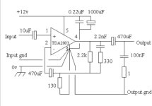
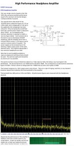
I would like to make a headphone amp with TDA2003 but as a current driven amp.
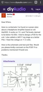
Found this topic in diy audio forum:
https://www.diyaudio.com/community/threads/old-school-tda2003-headphone-amp.257582/
Also found in the web archive some more information on it with measurements.
https://web.archive.org/web/20170103032351/http://g4oep.atspace.com/headamp/headamp.htm
Any idea if the basic current feedback can be applied to this TDA2003 headphone amplifier?
I added the previous schematic of a TDA2003 converted to current drive as attachment.
Attachments
-
 Screenshot_20240101_044927.jpg129.7 KB · Views: 114
 -
 Screenshot_20240101_044912.jpg181.9 KB · Views: 118
 -
 Screenshot_20240101_044956.jpg122.6 KB · Views: 110
 -
 Screenshot_20240101_044843.jpg224.9 KB · Views: 119
 -
 TDA2003-currentdrive--------42.gif9.2 KB · Views: 132
 -
 Screenshot_20240101_043125.jpg32.5 KB · Views: 128
 -
 tda2003 hp amp.JPG285.5 KB · Views: 118
 -
 Screenshot_20240101_050003.jpg139.1 KB · Views: 109
 -
 Screenshot_20240101_045939.jpg216.7 KB · Views: 117
All the discussion above applies to chipamps driving speakers, and the standard easy/practical solution is to make the NFB network out of the speaker in series with a grounded low value resistor, then taking NFB signal from their junction.
So far so good, also applies to Stereo amps, where each speaker has its own ground reference resistor .
2 speakers: 4 wires.
BUT with headphones norm is 3 wires 😱 : +Right, +Left and common ground.
You can open the plug , split wires and turn it into a 4 wire system, but then you will need an incompatible connector, both at headphone and amplifier.
That said , my experience (and most everybody else's) with headphones driven from a high impedance is ugly raspy tiring sound, not sure that is a worthy goal.

Thank you for your advice.
So the simple change in 266 post would work. Was not sure for this as pin 2 on the TDA2003 for headphone is wired a bit different than usual.
With the TDA2003 in voltage mode the stereo grounds can be connected to Mono but in cfa mode not?
However changing / separating output at the headphones could be possible and maintaining compatibility by making an adaptor combining it back again for standard amplification if needed.
Concerning Sound of cfa for headphones - is it ugly on all headphones?
As there is already discussion on projects for such amplification
https://www.diyaudio.com/community/...ne-amplifier-easy-project.393888/post-7452278
Last edited:
Would like to find out about how this TDA2003 based headphone amp was wired for practical use.
On the design here is more to be found
https://www.gammaelectronics.xyz/ax_03-2008_flea-headphone-amp.html
The man who published it was Andrew Smith

On the design here is more to be found
https://www.gammaelectronics.xyz/ax_03-2008_flea-headphone-amp.html
The man who published it was Andrew Smith
Preparing to realize Adasons concept of a LM3886 amplifier in current drive mode with XY board.
Ordered genuine Lm3886 from serious retailer in germany called reichelt.
Ordered meanwell 36volt smps 2x for +36 and -36 power supply and PC processor coolers for the transistors.
Will have to find out how to fix them onto the chips. Hope I will get an idea. Maybe someone knows how to already?
Everything will be put inside this wooden box and for operation it will be opened for air circulation. Like old grammophones.


its the Meanwell LRS 75-36. Its 2A, more would be certainly better. And I would have to measure if there is continuity between their ground and V-, if not, they could be used as power supply:
36+
0
36-
Here is Adasons easy description how to do:
https://www.diyaudio.com/community/...fication-to-current-drive.389985/post-7116567
I need an amp with more watts for a pair of Pfleid FRS20 fullrange loudspeakers.
Its one of the best fullranges ever made with three indirect tweeters.
With current drive I will adjust them new in their frequency response measurement assisted.


Ordered genuine Lm3886 from serious retailer in germany called reichelt.
Ordered meanwell 36volt smps 2x for +36 and -36 power supply and PC processor coolers for the transistors.
Will have to find out how to fix them onto the chips. Hope I will get an idea. Maybe someone knows how to already?
Everything will be put inside this wooden box and for operation it will be opened for air circulation. Like old grammophones.
its the Meanwell LRS 75-36. Its 2A, more would be certainly better. And I would have to measure if there is continuity between their ground and V-, if not, they could be used as power supply:
36+
0
36-
Here is Adasons easy description how to do:
https://www.diyaudio.com/community/...fication-to-current-drive.389985/post-7116567
I need an amp with more watts for a pair of Pfleid FRS20 fullrange loudspeakers.
Its one of the best fullranges ever made with three indirect tweeters.
With current drive I will adjust them new in their frequency response measurement assisted.
"Ordered genuine Lm3886 from serious retailer in germany called reichelt." I am getting cognitive dissonance there.
Quick doodle just for fun (never tried this before).
Chip amp with resistive load and current drive. As expected constant output,

Now with a fairly tough load, B&W 703 with 3 ohm impedance minima. Again this shows voltage out from the amp. Pretty massive variation from 12db to almost 30db. That has to sound massively different.

Carry on 🙂
Chip amp with resistive load and current drive. As expected constant output,
Now with a fairly tough load, B&W 703 with 3 ohm impedance minima. Again this shows voltage out from the amp. Pretty massive variation from 12db to almost 30db. That has to sound massively different.
Carry on 🙂
Yes, I know them all too well. I even used to buy directly from their shop in Oldenburg in the 80s and 90s when it still existed. I also had a fair bit of fake transistors from them, especially when I had moved away and needed to mail order. That problem continued into the 00s when they were already ISO certified. I still use them from time to time but avoid ordering anything that is commonly faked.
if it lights up with 72volts then it will be fake
I want to build two amps and for one project I will use 36volt smps and 24volt meanwells for the other one.
Can I use a speaker protection? Which one is revommended?
I want to build two amps and for one project I will use 36volt smps and 24volt meanwells for the other one.
Can I use a speaker protection? Which one is revommended?
- Home
- Amplifiers
- Chip Amps
- Chip amp modification to current drive