Sure(?) Maybe read this up if you don't believe what I type..
Percentage-wise maybe. But it means nothing for audibility. I'd take pure 5% H2 (on peaks) any day over a splash of complex IMD patterns..
Two things:-
1. You don't get a splash of complex IMD patterns from cascading tube amplifying stages. The higher order products die away very quickly because of the trig identity.
As I said before, solid state amps work a little differently.
2. The BBC research labs in the 1960's investigated the objectionableness of high order products cf low order. By a series of carefully set up double blind auditions of equipement specifically engineered to produce controlled amounts of distortion, they showed conclusively that the order doesn't matter much. What matters is the total amount of energy in the products. See E R Wigan's articles in Electronic Technology April & May 1961 and elsewhere.
There's a lot of misconceptions about distortion. And lots and lots of woffle on websites.
Small amounts of neg feedback causes odd order and higher order products where none would exist without it. If complexity and order mattered, then small amounts of neg feedback would make amplifiers sound worse. Not true though. Neg feedback always makes amplifiers sound better. Vast quantities of 5-tube radios and radiograms were turned out in the 1940's and 1950's with feedback ranging for about 3 dB to around 15 dB. And those of us who used to service that equipment know that disconnecting the feedback always made it sound worse.
The higher order products die away very quickly because of the trig identity.
Which one, this
This fact comes from the well known trig identity:
k . SIN(A)SIN(B) = k/2 COS(A + B) - k/2 SIN(A - B)
Or this
Which in turn becomes
k sin(A) sin(B) = (k/2) cos(A - B) – (k/2) cos(A + B)
😀
Re Popilin,
I've already acknowleged the typo. It doesn't really matter, the principle is obvious and in the context of this discussion a sine wave is the same as a cos wave. The nature of the ear's detection mechanism means that we are oblivious to phase.
There's two other typos in my earlier analysis - they don't alter the conclusions either. And I was a bit loose with forms, as I thought just about everyone would remember the identity from high school and most would have seen the standard definition of a sinewave, V = k.sin(2pi.f.t + P).
To see what happens as product order goes up is perhaps better expressed this way:-
From sin(A).sin(B) = 1/2 cos(A-B) - 1/2 cos(A+B) (standard form)
We can adapt it as:-
k0.k1.sin(2pi.At).k2.sin(2pi.Bt) = k0.k1.k2/2 cos[2pi.(A-B)t] - k0.k1.k2/2 cos[2pi.(A-B)t]
Herre, k1 & k2 are the amplitudes of two nth order products from a preceding stage. K0 is the distortion factor of the given stage. Given that in any reasonable amplifier circuit, k0 << 1, k1 << 1 and k2 << 1, the n+1 order products resulting in the next stage are of amplitude k0.k1.k2/2 << << << 1 ie very small.
In cascaded tube amplifiers, higher order products die away very quickly, and effectively the 2nd order products in successive stages add and subtract.
In bipolar transistor circuits, the subtraction of 2nd order can be used to advantage: If the emitter currents of two common emitter cascaded stages are scaled in proportion to signal level, overall distortion is much less than that of either stage alone. See Mullard Reference Manual of Transistor Circuits, 2nd ed 1961.
A similar trick can be done with two cascaded triodes. However, because we don't have full freedom to scale the grid base of tubes, a resistive attenuator is needed between the two stages to make it work.
Last edited:
Would this include the suggestion that it is unreliable to expect the distortion from two stages to remain balanced with respect to each other, particularly where their characteristics change dynamically? Possibly including varying loads with level, grid currents or maybe even complex loads?There's a lot of misconceptions about distortion. And lots and lots of woffle on websites.
Would this include the suggestion that it is unreliable to expect the distortion from two stages to remain balanced with respect to each other, particularly where their characteristics change dynamically? Possibly including varying loads with level, grid currents or maybe even complex loads?
That's a very wide range of possibilities.
The onset of grid current causes various sorts of problems. For high quality audio, amplifiers should be engineered so that grid current never occurs, or if it does, it occurs quite above the clipping point so the user will wind back the volume due to the clipping distortion.
Ceratin types of distortion cancelling circuits, eg SRPP, only canel distotion effectively if the load is constant and equal to the load the circuit was designed for.
Loads that vary with level are unusual in high quality audio. What do you have in mind?
Though I was generalising, I guess there's voltage distortion in plate resistors although I guess that 2HD would be fairly additive with the stage for this.Loads that vary with level are unusual in high quality audio. What do you have in mind?
Maybe I was thinking more of a kink in the characteristic.
Yes, you can get significant 2nd order distortion in an anode load resistor, if the signal level across it is quite high, and its a carbon composition.
As a rule, don't use carbon composition in anode loads - not in phase splitters where the signal level is high, and not in preamps or early stages where carbon composion resistor current noise can be significant.
Carbon film is much better. Metal film just about perfect.
In tube amplifiers, the only curve kinking that could matter is tetrode kinking at low anode loads - and that is pretty much a non-problem.
Doesn't change the conclusions though.
Which conclusions?
the distortions of each stage get summed, not multiplied.
the higher products of early stages [...] get divided down.
the 2nd order products in successive stages add and subtract.
Maybe you need to decide first on what you like to tell us?
BTW, isn't a dividing down the same as multiplying with a factor < 1 ? 😛😛😀
If complexity and order mattered, then small amounts of neg feedback would make amplifiers sound worse. Not true though.[...] those of us who used to service that equipment know that disconnecting the feedback always made it sound worse.
A claim in stark contrast with the experience of many tube DIYers. The concensus seems to be that it's either tons feedback of or nothing. Small amounts tend to just increase the obnoxious by products of distortion.
GoldenBeer, There is no contradiction. You have reproduced the conclusions adequately.
I am aware that many believe that small amounts of feedback are bad. It has been a persistent misconception. But if that were so, why were millions of 5-tube radios and radiograms made with small amounts of feedback? Such devices were carefully engineered and evolved to avoid any unnecessary cost.
Did you look up E R Wigan? If not, you should. He was master of getting the bottom of things and asking just the right questions.
Can you find any journal article that describes a double blind audition test with controlled amounts of distotion of diffent types that confirms that samll amount of feedback are audibly worse than no feedback at all?
Markus Scroggie, a well known electronic jourmalist at the time, published an article in Wireless World in the 1940's, showing very simply that small amount of feedback raises odd and higher order harmonics. For any given harmonic order, there is an amount of feedback that maximises the level of that harmonic. Ever since then, there has been a misconception that small amounts of feedback are bad.
But this does not mean that the sustem is audibly worse at harmonic peaking. This is because nature's design of the ear means it is insensistive to harmonic distortion. What it IS sensitive to, exquisitely so, is intermodulation distortion.
And, because any amount of feedback linearises the transfer characteristic, the total energy in intermod products is always less. Tha's what counts.
Not my intention to derail off topic discussions, but what happened with OP's amplifier? 😕
I am still here 🙂
I have been enjoying reading through all the posts!!!
My "workshop" is a storage closet without any windows and no air conditioning. We are in the middle of a heat wave and it's oppressive in there🙁 I might move either my tools and stuff to an air conditioned room to work on my projects when I have more time. Hopefully tonight I can make some time to look at the amp again. It is one of the nicest Chinese amps I have seen, I got it for $250. If I change the topology it must still fit to the existing circuit board, which shouldn't be an issue. I have also been reading the oscillation in tube amps section from George to help me "sniff" out the oscillation. As suggested I might just re-solder the tube sockets and see if that fixes it.
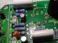
I tracked the oscillation back to the preamp section. I have continuity in feedback wiring from speaker tap and the 4k7 resistor is fine. I pulled the preamp board out because the solder joints look really bad. The picture really doesn't do it justice. The Power amp boards are much better in comparison. I will resolder all the tube sockets on the preamp board for both channels. Hopefully that does the trick.
Attachments
I wanted to update the thread and let everyone who helped know that the amp has been playing without any issues since I resoldered the sockets on the driver board.
I am open to suggestions for modifications now it's got a clean bill of health. I have a preamp and power amp project going so I am kinda all over the place.
I am open to suggestions for modifications now it's got a clean bill of health. I have a preamp and power amp project going so I am kinda all over the place.
If this is what you want, then you'd do better with this design (attached). It still bootstraps the gain stage to a higher gain while making for a shallow, low distortion loadline. It also provides a Lo-Z output, and lower than the SRPP. It also allows for larger output swing for the DC rail voltage.
It can be worked in two ways: the bootstrap capacitor can be sized to make it effective at all frequencies of interest. It can also be made quite small ( ~20pF ) so that this operates as an output buffered gain stage. The PFB becomes effective just on fast transients, with the capacitor acting as a "hurry-up" capacitor.
This topology can work very well. Depending on the design and chosen operating point, the cathode by-pass might not be necessary too.
I got this amp from China years ago and it has held up and sounded pretty good. Lately one channel has cutting in and out, loss of power, distorted sound. I found with the inputs shorted the right channel has a 50kHz oscillation. I do see an inductor that might be for an SMPS on the side with problematic channel.
Is the first stage and SRPP? If it is why? I thought they were good for driving heavy loads.....looks like it's driving 470k? I do remember reading that with the correct load they can cancel distortion like any push pull stage.
I would check these things first:
1 - Check that the coupling capacitors are not conducting DC. This is easy to do with the amp OFF using a DMM.
2 - Check to see if all connections from the input through to the end stage are good. Check ground connections too of course. Use a DMM with the amp OFF.
3 - Very carefully record all rail voltages with the amp on. only use ONE hand to hold your probe. Make sure your DMM is earthed. Keep your other hand behind your back.
4 - record all the voltages and put them in your schematic.. check if they make sense using Ohm's law.. etc..
I wanted to update the thread and let everyone who helped know that the amp has been playing without any issues since I resoldered the sockets on the driver board.
I am open to suggestions for modifications now it's got a clean bill of health. I have a preamp and power amp project going so I am kinda all over the place.
Glad to hear this!!! 😀
If you're happy with the sound, then just leave the "SRPP" stage as is... That's my advice. 😉
Glad to hear this!!! 😀
If you're happy with the sound, then just leave the "SRPP" stage as is... That's my advice. 😉
Yes it sounds good to me🙂 I do plan on leaving it as is for the time being, too many projects going anyway.
Thanks!
- Status
- Not open for further replies.
- Home
- Amplifiers
- Tubes / Valves
- Chinese amp Oscillation