All this talk about HV, and getting zapped, or even killed. I've yet to see anyone mention a safe method of insuring the filter caps are bled off.
So here goes: I use a "chickin stick". It's simply a plastic rod, about 2 feet long, with a resistor longitudinally affixed to one end. A wire about 2 feet long soldered to one lead on the resistor, with alligator clip on other end of wire. The opposite lead on the resistor protrudes like a probe. Clip to ground, and "probe" the HV out for a few seconds, and caps will be discharged, rendering the PS safe to work on. My particular probe is a 10w 50k resistor. I use it on KV + supplies. I suspect for the average audio amp supply a 10k-20k resistor would work just fine. The higher the resistance, the longer it takes to bleed off, but smaller spark on first contact.
If you like fireworks, you can just "crowbar" it with a screwdriver, but I would not reccomend that. 😉
Good method for discharging a CRT, too man.
I just use cheap gator clips and a 5k resistor (unless it's a small cap, then I just short it). I don't work on kV levels though, only about 600V at the most 🙂
I just use cheap gator clips and a 5k resistor (unless it's a small cap, then I just short it). I don't work on kV levels though, only about 600V at the most 🙂
The chickin' stick is a good practice. I had something similar “in the day”. Mine was a very stoutly made plastic drinking straw that I got from some carney someplace, about 18 inches long (450 mm). In the tip, I fitted a string of 5 kΩ, 2 watt resistors.
5 of them or something. I don't remember now.
Out the “bûtt end”, was the well insulated piece of stranded zip-cord wire, and a good heavy-duty pair of spring-clamps on the end. 6 feet of power cord! I'd leave one clamped to something earthy. The other was clamped to the device chassis or circuit-board ground. Worked wonders.
Now that I think back, I think I used a string of 15 ea, 680 Ω, 2 watt resistors. I had found a box of ancient carbon-comp ones at a yard sale. 25¢ for the lot.
Lastly, I soldered onto the 'hot end' an old tip-and-sleeve of a multimeter probe. It fit perfectly as well into the stout plastic tube. A bit of plastic-glue, and it was as solid as a rock.
-= GoatGuy ✓ =-
________________________________________
PS: it is always an outstanding idea to permanently install 100-to–2,200 kΩ resistors across EACH hi-volt capacitor if the layout permits. Keeps the lil' cretins from re-developing a charge when you're not looking. Can't tell you the number of times I've been zapped days later by a power supply cap which 'redeveloped' its charge. Evil, capacitors. Evil.
Last edited:
Keeps the lil' cretins from re-developing a charge when you're not looking. Can't tell you the number of times I've been zapped days later by a power supply cap which 'redeveloped' its charge. Evil, capacitors. Evil.
Those magical diëlectric properties, again. 😀
I always solder a 2 watt 220k resistor across the reservoir capacitor. I tend to use as little capacitance as possible in my power supplies, so they are typically fully discharged in under a minute. Don't forget to double check! If applicable, you can also shut the high tension off while keeping the filaments lit for a faster drain. Don't forget to double check!
I run an LED from the B+ as a visual indicator that there's still charge 🙂 20ma RED LED and around 500k resistor 🙂
Those magical diëlectric properties, again. 😀
Love the umlaut on the e. Diëresis. diëlectrics … now added to my 'auto diëresis preprocessor!'.
(Somewhat self-congratulatory, but it does hundreds of things, like detecting 'dieresis' and converting its first 'e' to 'ë'.
Or taking CO2 and converting it automatically to CO₂. Or ethanol .. C2H5OH, to C₂H₅OH. Or something wicked like Ca2MgAl(SiO4)4⋅4(H2O) … to Ca₂MgAl(SiO₄)₄⋅4(H₂O) … without requiring hard-to-type input, other than using conventional chemical-typing-in rules. Pat, pat, pat. )
Thanks.
GoatGuy
Last edited:
I always solder a 2 watt 220k resistor across the reservoir capacitor. I tend to use as little capacitance as possible in my power supplies, so they are typically fully discharged in under a minute. Don't forget to double check! If applicable, you can also shut the high tension off while keeping the filaments lit for a faster drain. Don't forget to double check!
Good advice. Since most hi-volt electrolytic 'cans' don't inexpensively come higher than 500 V, that's a good compromise.
P = IE and
E = IR so therefore
P = E²/R
… = (500 V)² ÷ 220,000 Ω
… ≈ 1 watt
For lower value power supplies, I just tune the resistor lower, per the above.E = IR so therefore
P = E²/R
… = (500 V)² ÷ 220,000 Ω
… ≈ 1 watt
-= GoatGuy ✓ =-
0,02A x 0,02A x 500= 200W (!?) 2mA probably? Still takes 2W…
What on earth is that for? Either
P = IE and E = IR so…
P = I²R and also
P = E²/R
P = IE
P = 500 × ²⁰⁄₁₀₀₀
P = 10 W
Right?P = 500 × ²⁰⁄₁₀₀₀
P = 10 W
Just Saying,
-= GoatGuy ✓ =-
What on earth is that for? Eitherso with 20 mA and 500 V
P = IE and E = IR so…
P = I²R and also
P = E²/RP = IERight?
P = 500 × ²⁰⁄₁₀₀₀
P = 10 W
Just Saying,
-= GoatGuy ✓ =-
Got a new Casio with a surprizing shuffle of the interface but... if someone would be running 20mA through a 500K resistor the power involved would be I²R indeed. Practically the LED would be close to 0,1mA or thereabout.
Got a new Casio with a surprising shuffle of the interface but… if someone would be running 20mA through a 500 kΩ resistor the power involved would be I²R indeed. Practically the LED would be close to 0,1mA or thereabout.
Yah, ok… but continue on.
²⁰⁄₁₀₀₀ A × ²⁰⁄₁₀₀₀ A × 500,000 Ω = 200 W
but what's the voltage?E = IR
E = ²⁰⁄₁₀₀₀ × 500,000
E = 10,000 V!
I'm betting that that voltage is rather significantly higher than you were probably thinking about at the outset, right?E = ²⁰⁄₁₀₀₀ × 500,000
E = 10,000 V!
Just Saying,
-= GoatGuy ✓ =-
( 0.1 mA = 0.0001 A )² × 500 kΩ = 0.005 W, or 5 milliwatts.
Last edited:
True. So, a 2mA LED will give the same light intensity here as the 20mA?
Rarely. Almost never. Until an LED so-called PN junction reaches carrier saturation, the light output is surprisingly linear with proportional changes in current. 2 mA will be ¹⁄₁₀ as bright as 20 mA, on an LED which is rated or 50 mA. But 2 mA will only be ½ as bright as 20 mA on a part nominally rated for 10 mA forward current. Carrier saturation. And the LED life will be shortened. Perhaps from decades to weeks. Perhaps minutes. Don't go there.
Just Saying,
-= GoatGuy ✓ =-
Clear. I was thinking about the situation at hand, a LED dangling at a 500K resistor. Old fashioned LEDs took 2,0V and 5mA if I remember right (400 ohms). If these 20mA newbies are meant to run from the same 2,0V their internal resistance is 100 ohm. With 500V over the two resistances, current 1 would be 500V/500.400R=0,9992mA. Current 2 would be 500V/500.100R=0,9998mA. Which LED gives the most light?
Clear. I was thinking about the situation at hand, a LED dangling at a 500°K resistor. Old fashioned LEDs took 2,0V and 5mA if I remember right (400 Ω). If these 20mA newbies are meant to run from the same 2,0V their internal resistance is 100 Ω. With 500V over the two resistances, current 1 would be 500V/500.400R=0,9992mA. Current 2 would be 500V/500.100R=0,9998mA. Which LED gives the most light?
Remember it is a diode first and foremost.
While I could dive-deep and get all technical (i.e. recalling that current flow thru a semiconductor diode is an exponential function relative to the forward-voltage thru the junction, the Boltzman constant, absolute temperature in Kelvin, and some magic sauce correction factors…), or I could summarize it like this
VF ≈ u;
whereu depends heavily on the P and N materials making up the junction
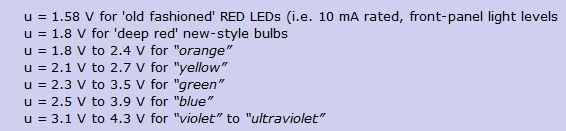
Now, making that quantitativeu = 1.58 V for 'old fashioned' RED LEDs (i.e. 10 mA rated, front-panel light levels
u = 1.8 V for 'deep red' new-style bulbs
u = 1.8 V to 2.4 V for “orange”
u = 2.1 V to 2.7 V for “yellow”
u = 2.3 V to 3.5 V for “green”
u = 2.5 V to 3.9 V for “blue”
u = 3.1 V to 4.3 V for “violet” to “ultraviolet”
Why the variation? Well … because of process-and-implementation-and-forward-saturation 'settings'. We need this thing called “the band-gap” energy to produce light centered around a particular average color. One can dig-into-physics to show that the energy of 'red' light is about 1.3 eV, and for ultra-violet around 2.7+ eV. The diode's bandgap must be at least that high. But after that, there are “intrinsic differences” in semiconductors. Silicon is quite a bit different than gallium phosphide, or gallium aluminum nitride. Or the even more exotic species employed to output smaller (more blue) and smaller wavelengths. And… for applications of REALLY bright output — traffic stop lights — even the RED emitters avoid the 'easy' gallium arsenide quantum system, and use the exotics for ultra-efficient output. u = 1.8 V for 'deep red' new-style bulbs
u = 1.8 V to 2.4 V for “orange”
u = 2.1 V to 2.7 V for “yellow”
u = 2.3 V to 3.5 V for “green”
u = 2.5 V to 3.9 V for “blue”
u = 3.1 V to 4.3 V for “violet” to “ultraviolet”
So, in a nutshell, “it depends” is the best answer.
Sorry.
A rubber duck answer.
-= GoatGuy ✓ =-
PS I almost forgot ... that the point of a diode is to remember that its forward voltage VF is nearly a constant over a broad range of current-flows thru it. You can vary the current 10 to 1 or even more ... and the VF might only change 15%. Nearly constant. LED diodes are even more stable than conventional rectifier diodes, since their VF is way more related to delivering a certain color-of-photons than just simply rectifying large amounts of current.
Last edited:
Ya, I should have clarified but I thought it was obvious that the resistor limits the current to far less than the rating of the LED.
So, when the LED illuminates we find a certain forward voltage. This voltage comes from a current running through a resistance. For this voltage to be quasi constant, the LED must vary resistance with alternating current.
LED and other semiconductors are used to bias tubes. The cathode resistance would be in parallel to this varying LED resistance, I guess. How come people are so enthusiastic about (the effects of) this form of biassing? I can imagine a 75% drop in cathode resistor value (LED vs RK) can be noticed because of lower ra.
LED and other semiconductors are used to bias tubes. The cathode resistance would be in parallel to this varying LED resistance, I guess. How come people are so enthusiastic about (the effects of) this form of biassing? I can imagine a 75% drop in cathode resistor value (LED vs RK) can be noticed because of lower ra.
Last edited:
- Home
- Amplifiers
- Tubes / Valves
- chikin stick