What does any of that mean? I dont understand...
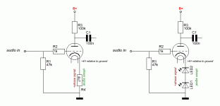
Biasing with a LED is setting the voltage between cathode and grid to the Vf of the LED.
The quiescent anode/cathode current results from the B+ volts and anode load resistance, at the grid volts set by the LED.
The Cathode resistor isn't needed with LED, the resistance of the cathode may well change some with LED bias, I dont know
Last edited:
So, when the LED illuminates we find a certain forward voltage. This voltage comes from a current running through a resistance. For this voltage to be quasi constant, the LED must vary resistance with alternating current.....
Shockley's Law. The "resistance" *depends* on the current. It is not a classical (Ohm) pure resistance.
It is perhaps better to picture the voltage drop like a waterfall. There is a drop in my ditch where it goes over bedrock. Say that when water flow is very low the drop is 1.5 inches. And when water flow is Big the drop is 1.9 inches. This may be 100X the water flow, for only 30% change of drop. Niagara Falls is 51 meters according to the books. It may go 52m in spring floods and 50.5m when they turn the Falls down to a trickle (they do that).
LED biasing is essentially a quasi constant voltage, not much influenced by the cathode current. Yes, LEDs are nonlinear devices, but in this case we use it for our benefit.So, when the LED illuminates we find a certain forward voltage. This voltage comes from a current running through a resistance. For this voltage to be quasi constant, the LED must vary resistance with alternating current.
LED and other semiconductors are used to bias tubes. The cathode resistance would be in parallel to this varying LED resistance, I guess. How come people are so enthusiastic about (the effects of) this form of biassing? I can imagine a 75% drop in cathode resistor value (LED vs RK) can be noticed because of lower ra.
For Cathode bias, you can use an LED, a Zener, a silicon signal diode(s), or a silicon rectifier diode(s).
Just do not use a Tunnel Diode. You will get jumping states in an oscillating manner.
But you may never see the low current point in the middle (quicker than many scopes).
Just do not use a Tunnel Diode. You will get jumping states in an oscillating manner.
But you may never see the low current point in the middle (quicker than many scopes).
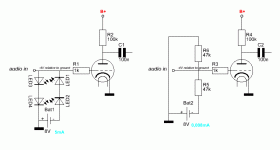
Your LEFT drawing, won't work, period.
Your RIGHT drawing, is … curious … and presents a 24 kΩ load to the source. IF that is what you want, then its fine.
The 'point' of an LED bias (in series with cathode) is that it raises the cathode voltage by a surprisingly-near-constant amount regardless of the input signal. From the cathode-grid-anode perspective of a valve, it “feels like” the grid has been dropped (made more negative) compared to the cathode. The VA-K voltage is diminished a little bit by the string of LEDs in the cathode series arrangement.
Sigh…
It really is that simple.
And as A3sUMMER sez… you can use a string of ordinary diodes, rectifiers, an appropriately sized Zener, … etc …
However, do note that the use of a chain-of-ordinary-diodes has the distinct disadvantage of summing all of their temperature-variation dependencies. Turns out not to be very much in practice for cathode-string bias situations, but for more demanding service, only modestly-low voltage Zeners are tuned to have “zero tempco”¹;
Just Saying,
-= GoatGuy ✓ =-
________________________________________
¹ “tempco” is engineering lingo for “coefficient-of-change as a function of temperature”.
Not so fast Goat 😉
The interesting part here might be in the explication why the left drawing won't work. I see a network with low impedance to ground, forming a high loss for the audio signal. But what exactly happens to the audio signal? Does it get rectified by the LED, so positive phase runs through LED3+4 to ground and negative phase through LED1+2 plus bat1?
The interesting part here might be in the explication why the left drawing won't work. I see a network with low impedance to ground, forming a high loss for the audio signal. But what exactly happens to the audio signal? Does it get rectified by the LED, so positive phase runs through LED3+4 to ground and negative phase through LED1+2 plus bat1?
The reason I try to understand the exact working is with the existance of negative feedback in the unbypassed cathode circuit. If we consider the audio signal here, a form of rectification* would occur with LEDs. From the bigger power supply example we know that interelectrode capacitance plays a role. How would that translate to the fidelity of the signal taken from the anode? As you set me straight Rk is in series with ra for output impedance, the added difference being u+1 times Rk.
Attachments
Last edited:
- Home
- Amplifiers
- Tubes / Valves
- chikin stick

