I'm still not seeing it. The link relates to A to D conversion. If it's already digital, you'd have to first upscale the sampling rate of the input signal to make room for higher frequencies (not sure why you want to do that in the first place), and then forget to low-pass filter them out before down-sampling again.
Maybe you missed the caption under the plot I mentioned? It says:
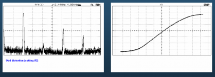
That has nothing to do with A to D conversion. It was all done in the digital domain.This is a frequency-time plot of a simple sine sweep with harmonic distortion added using Reviver's serial mode with the alias filter turned off. You can see how the aliases are bouncing between zero and the Nyquist frequency.
And from the other link I posted:
Specifically : "If a digital algorithm produces frequencies which are actually higher than the Nyquist frequency of the system, then aliasing artifacts are generated"
Nothing about A to D conversion in there. They are talking about a digital algorithm, in the digital domain.
Aliasing
Under certain conditions, aliasing might appear. The aliasing effect is a pure digital effect and is always related to a frequency bandwidth limit. If a digital algorithm produces frequencies which are actually higher than the Nyquist frequency of the system, then aliasing artifacts are generated which usually folds back into the supported bandwidth and so gets visible in the spectrum. The usual method to avoid this is to increase the sample rate. Sometimes, aliasing is hard to spot in the visible spectrum and that is when it’s masked by harmonic distortion.
Specifically : "If a digital algorithm produces frequencies which are actually higher than the Nyquist frequency of the system, then aliasing artifacts are generated"
Nothing about A to D conversion in there. They are talking about a digital algorithm, in the digital domain.
It's true (what you mentioned) that one could upsample by a large factor, create the haromonics, lowpass filter, and then downsample but that is not something that can be done within a LADSPA plugin.
I did some more thinking and planning last night. Unfortunately I think I have found a "flaw" in the otherwise sweet, sweet ointment...
It turns out (this was alluded to before) that you can use the Chebychev polynomials to determine the ratios or coefficients for each term in a polynomial that generates harmonics from the incoming signal. For example, x^2 generates some amount of second order harmonic. Higher order terms generate even or odd order harmonics of that order and lower, for example x^5 generates 5th and 3rd harmonics, not just 5th. The Chebychev polynomial accounts for this, and has terms that add or subtract various amounts of each order to produce the amount of each you want.
The problem is that they only do that exactly when the signal is a sine wave of amplitude 1.0. When A<1.0 the harmonic components are reduced, and it looks like that is by the factor of (1/A)^(N-1) where N is the Nth harmonic. At least I think this is the relationship. Anyway, I originally thought that one could just determine A from analysis of the incoming signal and then compensate the levels of each harmonic follow that relationship to correct the harmonic levels back to what was intended. Otherwise what happens is that the harmonics are strongly level dependent, more so as the order of the harmonic increases. So, the problem is that this would be possible only if the input was just a sine wave of a single frequency. A music signal is basically a whole bunch of sine waves at all frequencies, the amplitude of which are varying with time. It's not really feasible to track the amplitude as a function of frequency and then how could you only adjust the polynomial for each without creating many, many bands and having a sidechain for each... it just compounds the problem by a huge factor making it too computationally intensive. So strictly speaking this approach cannot work "perfectly".
On the other hand, if we can just live with "sort of close enough" it might be enough to just track the overall signal level and make the crude assumption that level is the same for all frequency components. This is far from correct, but it would allow for some ballpark correction of the harmonics. It might work, or it might not. I would have to think about it and whether it is worth putting in all the coding time to find out.
So, getting back to this idea (my original one)...I would start by creating a working system first, something like:
Sampled input --> lookup table --> modified output.
What is attractive is that the algorithm is very simple, both programmatically and computationally speaking. There is an input-output relationship that is responsible for adding distortion. It distorts the waveform by multiplying each sample by a factor that is a function of the sample's value on the interval [-1, 1], which is the range of "in bounds" values for digital audio on a computer. Since these values are streaming through the LADSPA plugin as floats, you just need to define the relationship or "curve" that will be applied and perform one multiplication per sample. It doesn't get any easier than that!
The problem is with the generation of the harmonics. These will alias if their frequency is above the Nyquist frequency of the sampled data. As I think Abstract brought up before, you can upsample the data, apply a lowpass filter to that data to limit the incoming bandwidth, apply your distortion "curve" to generate the harmonics, again apply a lowpass "anti aliasing" filter, and finally downsample back to the original rate. On paper that sounds like it would work. I think in practice it would not unless the upsampling factor is very high. The reason is that I am not sure you can easily control which harmonics are produced by these curves, and so the user (especially a naive one) may still generate harmonics that are high enough to alias. It might be possible to limit how the curve is specified, not sure. I am not very familiar with the topic to know exactly. But let's throw caution to the wind for a second and say that we can either limit higher order harmonics or we can oversample with a high enough factor to accommodate them. Writing the processing part of the plugin is a snap. Making it possible to read in a lookup table is not as easy, but it can be done. It could be hardcoded into the plugin, and when you want to change the table you have to recompile. That would be easy. Recompiling is done (in my plugins) via a makefile. The only dependency is the LADSPA SDK itself, which is found in all the usual repositories. But what the plugin absolutely cannot do is the upsampling, downsampling, and filtering tasks. LADSPA plugins must be computationally lightweight, and resampling "ain't".
But! It might be possible to do these tasks outside the plugin as other processing on the LADSPA host. Not sure. The user would need to be instructed how to put that together. It leaves lots of room for abuse/misuse by lazy or uninformed (people who don't bother to read the documentation) users. But when done properly it might work just fine.
So we are back to considering the "transfer function" relationships that are discussed in the Pete Millet "Magic Box" article as a way to generate the harmonics:
https://www.ka-electronics.com/images/pdf/ThesoundofDistortion.pdf
Let's say we want to accommodate up to 10th order (just choosing an arbitrary round number here) harmonic and we assume there will be no harmonics higher than 10th order produced by the transfer function. If we want to process the full audio bandwidth up to 20kHz this means that 10x 20kHz = 200kHz must be accommodated below the Nyquist frequency and thus the upsampled rate must be at least 400kHz. A bit higher would be good. Does your LADSPA host allow you to upsample to such a rate?
A slightly modified approach might allow for lower upsample factors. It depends on the answer to this question:
What is the highest frequency from which you want to generate harmonics?
Above I suggested that the audio signal should be low-passed at 20kHz before upsampling. This frequency has a direct relationship to the rate needed when upsampling. But let's take another look at what is being done: we are generating harmonics at higher frequencies than the original signal. Humans can only hear up to 20kHz and this falls as you age (I'm in my early 50s and can only perceive up to about 14kHz). The lowest order harmonic (second order) doubles the frequency. So why would we bother to use audio above 10kHz as input to the harmonic generating transfer function? Even as low as 10kHz, the harmonics generated from this frequency are are all above our range of hearing.
With that said, one could consider this modified method:
The incoming audio is split into low and high bands via lowpass and highpass filtering at e.g. 5 or 10 kHz. Only the lowpassed part is upsampled and fed to the harmonics-generator LADSPA processing. The output of this is then lowpass filtered and the downsampled. Finally the highpassed part of the original signal is summed with the processed audio. The LP-HP filter pair used to initially split the incoming audio would need to be chosen such that they sum back together properly and do change alter the audio (e.g. adding phase distortion, etc.) which may require FIR linear phase filtering. This might be OK because the frequency is high so the kernel is not large and delay would be short.
What the above would buy you is the ability to:
1. reduce the rate for upsampling by 2x or 4x, and
2. Keep content above 20kHz that was present in the original audio signal.
The downside with this approach is that it adds a good bit of complexity.
As before, only the distortion generation would be done within the LADSPA plugin that I write. All other tasks would need to be set up by the user outside of that, under the audio host/processing program.
What about something like modelling a MOSFET transfer function, but reducing the gain to 1?
The 'gate' input gets modified, sample by sample, by a 1d lookup table to produce a 'drain' output.
For a 44.1k sample rate, the max rate of oscillation is 22.05kHz, and something that looks like 'aliasing' could likely be a real effect, such as a DC (or low frequency) offset if, for instance, the top halves of sine waves are stretched.
Just one note on the split stream approach I described in post 28. I forgot just how compact an FIR filter can be if the frequency is high WRT the sample rate. For example, I designed a linear phase FIR filter with 80dB of attenuation and a flat passband to 7kHz, stopband beginning at 10k Hz. This is only about 48 taps when the sample rate is 48kHz. That is small enough to do by direct convolution, no FFT needed. That might be something I could code into a LADSPA plugin after all, and the linear phase (constant delay) property would be very helpful.
So, I have figured out how to implement the transfer function in code. Initially I will have the user define a static array in the code that consists of pairs of numbers (x,y) spanning the interval (-1:1,-1:1). These points define the transfer function. The user can supply as few or as many as they want. I will then interpolate these into an internal lookup table using a montonic spline on to a fixed grid of either 100+1 or 1000+1 points on two intervals, -1 to 0, and 0 to 1, including both end points. A monotonic spline must continually increase, and this prevents the interpolated values in between user defined point from looping/arcing in non-sensical ways. By performing the interpolation separately for positive and negative regions it is easier to model, for example, a class-B amplifier where the devices do not conduct near zero signal level. The other convenient thing about using a round base 10 number of points is in the ease of "looking up" the value in the table. Each sample is the x value we want to look up, and the output will be the corresponding y value. When the x value is, e.g. 0.123456789..., I can simply parse the digits in the number to directly obtain the position of the two nearest x values in the table, the one below is at position 123 and the one above is at position 124. I will then perform a simple linear interpolation on these two values to get the corresponding y value. This avoids the task of looking up a value in a list or table, which requires O(log N) operations by bisection for example. Since this has to happen for every sample passing through the plugin, it is worth saving these few operations each time. This approach can be used when the number of values is not a power of 10 but that would take some thinking and I am lazy!
So, the plugin is simply taking an incoming sample value, finding two bracketing values in a LUT, and then interpolating those to get the output sample value. That will be nice and lightweight, perfect for the LADSPA plugin.
I have attached a pic of such a transfer function. It's just a curve, like the one shown at right in the image. The shape of the curve determines the distortion products produced as a function of the signal level. This can be measured for an actual physical amplifier.
As a reminder, the user would still be responsible for performing the other associated and necessary tasks I outlined before, including low-pass filtering and upsampling of the incoming signal, and then (if desired) downsampling after processing the data with the plugin.
Attachments
Last edited:
I've been doing some more thinking about the aliasing. There are probably some cases where, at a high enough 'carrier' frequency, the curvature in the LUT could give an incorrect DC offset - the aliasing. This could be compounded by actual low frequency content in the signal, which would appear to give incorrect IMD results as well.
So, I'm thinking, build the LUT into the interpolator itself rather than making them 2 separate things. Going from 1 sample to the next, the LUT already supplies the correct weighting for the in-between values being traversed.
Some sort of polynomial curve fitting would require a buffer of however many samples you want for the interpolator.
Last edited:
Dc offset has absolutely nothing to do with aliasing. It's very easy to create DC offset via the transfer function curve but one can always highpass the output at some suitably low frequency using an IIR filter to get rid of the DC component.
Yes, that is another reason why I am taking the approach that I described above.the LUT already supplies the correct weighting for the in-between values being traversed
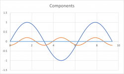
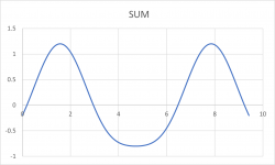
I did some testing of the concepts in Excel to see what happens. After some playing around I discovered that I could use the Chebychev polynomials to create the transfer function curve. The sum of the fundamental and all harmonics generated via Tn(x) is divided by the fundamental to obtain the transfer function. The Chebychev polynomials work nicely and I can generate various TFs that would make sense. An example is attached. In this example I added 20% "positive phase" second harmonic.
What's nice about this? I can still organize the program to generate distortion from the transfer function curve. This can be whatever curve you want. But it is possible to create the transfer function with only specific amount of the desired harmonics via the Chebychev polynomials. This is not easy to do otherwise. And it still provides the possibility of measuring the transfer function of an amplifier and then duplicating that with the plugin.
What's nice about this? I can still organize the program to generate distortion from the transfer function curve. This can be whatever curve you want. But it is possible to create the transfer function with only specific amount of the desired harmonics via the Chebychev polynomials. This is not easy to do otherwise. And it still provides the possibility of measuring the transfer function of an amplifier and then duplicating that with the plugin.
Attachments

But it is possible to create the transfer function with only specific amount of the desired harmonics via the Chebychev polynomials
IMO the condition for signal component amplitude equal to one still applies.
Ad your piecewise transfer function - ESS ADCs (e.g. ES9822/4) configure their internal static distortion compensation by splitting the <-max, +max> range to 64 bands, and providing registers to configure offsets to the TF at those levels. In between the samples are linearly interpolated. The TF is a broken line/polyline.
I use a piecewise cubic spline (matlab/octave splinefit() for generating, ppval() for applying) for generating TF for static distortion compensation https://www.diyaudio.com/community/...ion-for-measurement-setup.328871/post-6527152
A signal equal to the sample rate will produce a DC offset. Good luck with your project. unsubscribing from the threadDc offset has absolutely nothing to do with aliasing. It's very easy to create DC offset via the transfer function curve but one can always highpass the output at some suitably low frequency using an IIR filter to get rid of the DC component.
Yes, that is another reason why I am taking the approach that I described above.
@phofman Yes, level dependency is probably not something that I can overcome. The only way would be to somehow come up with a measurement of the signal level. The problem is that we are not talking about a pure sine wave, but rather sines at all frequencies and each can be at a different level. So I will probalby not worry about this or maybe I will come back later once I have things working.
Speaking of the DC offset... wow, that is another nasty issue with this approach. And honestly I think I have reached the end of my enthusiasm for distortion generation. So, never mind.
- Home
- Source & Line
- PC Based
- checking interest: LADSPA plugin for generating euphonic or other distortion