I have written several LADSPA plugins to date. For the uninitiated, these are pieces of software that process audio under an audio "host" on computer hardware running a Linux OS. I use LADSPA plugins to implement DSP crossovers, and various other tasks.
Within certain DIY audio circles there seems to be an interest in adding a couple of percent of ear/brain-pleasing "euphonic" distortion, specifically 2nd order, to the playback chain. You know who you are. It's not really something I seek in my own equipment, but it might be fun and edumacational to experiment with the addition of distortion in a controlled way. Here is (potentially) one way to do that.
The idea is to define a transfer function that will be applied to the audio signal. The TF is just a "curve" that is the input-output voltage relationship. Samples come in, get multiplied by the transfer function, and then are spit out. The "curve" of the transfer function describes how the audio waveform will be altered. By defining the TF with various shapes you can create distortion with predominantly odd or even order harmonics and the extent to which the TF is curved away from the purely linear out=in sets the level of distortion that is added to the signal. The TF would be defined within the plugin as either a table of values to interpolate or an analytical function. The output signal from the plugin can be analyzed to determine the distortion level and harmonic distribution like any other signal. The TF data could then be shared with other users who want to implement it on their own systems. It might be possible to measure the TF of actual physical devices that have nice distortion signatures and them implement them in the plugin to get that "sound" out of your analytical equipment when you want that, and defeat it when you don't.
That's the basic gist of the nascent idea of a plan at least. Interest? Thoughts?
Some related info here:
https://www.ka-electronics.com/images/pdf/ThesoundofDistortion.pdf
http://www.till.com/articles/harmonicdistortion/index.html
Last edited:
One problematic aspect of implementing this idea is that, by definition, it will be creating new harmonics that will be higher in frequency than the input. This may cause the harmonics to be aliased. Let's say for simplicity we have a 10k Hz sine wave and we generate some harmonics. These will occur at N times the fundamental, and it is pretty easy to see that if your sampling rate is 44.1k or 48k Hz all harmonics higher than the second will become aliased because they will exceed the Nyquist frequency of the sampled audio data. I think this could be addressed in a couple of ways:
- Run the process at a high sampling rate, generate the harmonics as a side chain instead of on the main signal, and then low-pass filter the side chain INPUT before creating the harmonics. For example, run everything at 192kHz, copy the signal into the side chain and low-pass filter it at 10kHz, generate the harmonics on the portion of the signal that was below 10kHz, and then mix the side chain back into the main signal. Up to the 9th harmonic of 10kHz can be accommodated below the Nyquist frequency (96k Hz), and I would assume generating these high harmonics is not desirable anyway.
- Run the process at a high rate but filter the main audio signal hard at e.g. 20kHz, then generate the harmonics directly on the main signal and make sure that the transfer function does not create harmonics that would exceed the Nyquist frequency.
I'd love to see this. I've had plans to do this in DSP but, you know, life. Of the two approaches to dealing with aliasing, I think the first is more promising. Ideally, you'd have one brickwall per order of harmonic generated, the 2nd harmonic generator being limited to fs/4, the 3rd harmonic generator being limited to fs/6, etc. You wouldn't need a particularly high sample rate to do this, just pretty savage filters. Overall, the advantage of this approach to me is that you wouldn't need to upsample the input and decimate the output as you would with the second approach. You'd want to decimate the output down to the same rate as the input, right? So you could A/B the processed and unprocessed signal with identical downstream processing?
Typically, multiple (or all of the) harmonics are generated at the same time by the transfer function, so your idea of multiple brick wall filters likely won't work in practice. I suppose a bank of notch filters, like those used to notch out the fundamental when doing old style distortion measurements, but instead one at each harmonic frequency would be an option over a single low pass filter.
Also, you do need to use a high sampling rate or upsample before the process. This is because the harmonics must be accommodated in the signal below the Nyquist frequency to prevent aliasing. Actually, some aliasing is OK as long as the folded frequencies can still be filtered out.
I assume that people are not wanting to generate high order harmonics and this would not be a general tool for doing that. It's mostly useful for low order harmonics due to the aliasing issue. But those are exactly the ones you want.
I think what I would do is just create the harmonic generator part, in which the transfer function is imposed on the audio signal fed to it. Then the user can decide how to structure everything around that, e.g. what sample rate to feed it, how to pre-filter or post filter, etc. Those can all be done outside the plugin, and would leave the flexibility on how to do it up to the user. Some guidelines and suggestions on how to do that could be given in the plugin description.
Last edited:
This sounds interesting. Maybe emulation of a certain SET amplifier transfer function including the transformer could sound nice. How about including an option of the effect of limiting bandwidth - or that would be done better externally?
I should maybe have been more clear. What I'm suggesting is similar to your first option but involves several side-chains, not just one. So, instead of a single transfer function that generates all the harmonics, you have one process that generates 2nd order (based on squaring the input), another that generates 3rd (based on cubing the input), etc. Each generator would need its own brickwall ahead of it. This adds complexity, but it conceptually at least makes it easy to change polarity and mix the individual harmonics and in real time.
You don't need a high sample rate for this because the individual harmonic generators are individually bandwidth limited so their outputs can't alias.
You don't need a high sample rate for this because the individual harmonic generators are individually bandwidth limited so their outputs can't alias.
@lauda: So for each sidechain you mean to use a form like this:
out = in^N
where N is an integer, e.g. N=2 should produce the 2nd harmonic, and in general this is how you specifically generate only the harmonics you desire (by using only whatever set of N=2,4,6 etc. that you want)? Those would each be generated in a separate side chain and then mixed back into the main signal in whatever proportion you want? That's a great idea, actually. I guess this might be called "polynomial waveshaping" or something like that.
It's straightforward to apply steep LP filters at an appropriate frequency for each sidechain to limit what is fed to them and prevent aliasing. The sampling rate is known within the plugin, so the filter frequency can be based off of that.
The LADSPA plugin format allows the user to pass zero up to some max number (specified within the plugin) of parameters to it. These parameters could represent the amount that each harmonic component side chain is mixed back into the input signal as parameters. I should be able to program the plugin to do the rest automatically (create the sidechain for each harmonic component, pre-filter, etc.). That would make it very easy to use...
Last edited:
After some more reading, it turns out that using Chebychev polynomials makes it very easy to go from the specification of what percent of the Nth harmonic you wish to add to the generation of exactly that much in the final signal. Still need to use several sidechains each wtih their own anti-aliasing filter, but that all seems doable to me.
As I'm sure you've discovered, 2nd and 3rd are easy, but 4th and higher get a little more complicated: (sin(wt))^4 yields sin(4wt) and sin(2wt), 5th power yields 5th and 3rd harmonics, etc. But this is the basic idea!@lauda: So for each sidechain you mean to use a form like this:
out = in^N
where N is an integer, e.g. N=2 should produce the 2nd harmonic, and in general this is how you specifically generate only the harmonics you desire (by using only whatever set of N=2,4,6 etc. that you want)?
After some more reading, it turns out that using Chebychev polynomials makes it very easy to go from the specification of what percent of the Nth harmonic you wish to add to the generation of exactly that much in the final signal.
Chebyshevs are very good and precise, I use them in my distortion compensation POC for controlled distortion generator https://github.com/pavhofman/nonlin...4a76c25733b92fb91097a/octave/genDistortPoly.m
But IME the level of the generated distortion works precisely only for a single tone with amplitude exactly 1. I have to scale the samples to one, generate the distortions, and scale back to the original level https://github.com/pavhofman/nonlin...fb8ccca91bcf8c/octave/run_distortion.m#L9-L28
So for a general signal they do generate the required harmonics only, but at different levels than requested unless the given frequency component has amplitude 1. At least that's my experience.
@phofman Thanks for mentioning that. I have seen it called the "distortion index". This nice review of waveshaping described the effect:
http://musicweb.ucsd.edu/~trsmyth/waveshaping/waveshaping_4up.pdf
The signal level influences the amount of distortion produced by a certain vector of Tn(x). Higher signal produced more distortion for the same Tn(x) vector. Level dependent distortion is how some equipment (e.g. single ended tube amps) actually performs, so that may not be undesirable if mimicing their sound is what the plugin is aiming to do. Also, it might be better to use the input-output transfer function method of distortion production rather than using Chebychev polynomials.
If one wanted to maintain the same percentage of distortion products it might be possible to come up with a lookup table of the Tn(x) vector that is searched as a function of signal level. There is a Steve Harris LADSPA plugin that does this sort of thing. Here is the main audio processing loop (it is processing one block of length sample_count samples):
The signal envelope is calculated by taking the absolute value of the audio sample and then using a sort of running average, computed differently when the envelop is rising or falling. The envelope is like the distortion index I mentioned above. Then there is an interpolation of a look up table (cd_lut) based on this value. In this particular plugin the author wanted the distortion levels to rise with signal and the LUT encodes that behavior. The Chebychev vector is calculate using chebpc() to produce the vector of the Tn(x) coefficients, p[]. Then they use Horner's rule to efficiently compute the Tn(x) sum, storing the distorted value for the sample in y.
This is an approach worth emulating to some degree. I am not sure it could work for a general, user supplied set of harmonic distortion levels unless the lookup table can be computed from those values. I will have to think about it a little more. There was no anti-aliasing done, so that would need to be added into the code along with the sidechains, one for each power of x in the polynomial.
http://musicweb.ucsd.edu/~trsmyth/waveshaping/waveshaping_4up.pdf
The signal level influences the amount of distortion produced by a certain vector of Tn(x). Higher signal produced more distortion for the same Tn(x) vector. Level dependent distortion is how some equipment (e.g. single ended tube amps) actually performs, so that may not be undesirable if mimicing their sound is what the plugin is aiming to do. Also, it might be better to use the input-output transfer function method of distortion production rather than using Chebychev polynomials.
If one wanted to maintain the same percentage of distortion products it might be possible to come up with a lookup table of the Tn(x) vector that is searched as a function of signal level. There is a Steve Harris LADSPA plugin that does this sort of thing. Here is the main audio processing loop (it is processing one block of length sample_count samples):
C++:
    for (pos = 0; pos < sample_count; pos++) {
      const float x = input[pos];
      const float a = fabs(input[pos]);
      float y;

      if (a > env) {
              env = env * 0.9f + a * 0.1f;
      } else {
              env = env * 0.97f + a * 0.03f;
      }

      if (count-- == 0) {
        for (i=0; i<HARMONICS; i++) {
          interp[i] = cd_lut[0][i] * (1.0f - env * dist) +
                      cd_lut[1][i] * env * dist;
        }
        chebpc(interp, p);

        count = 4;
      }

      // Evaluate the polynomial using Horner's Rule
      y = p[0] + (p[1] + (p[2] + (p[3] + (p[4] + (p[5] + (p[6] + (p[7] +
          (p[8] + (p[9] + p[10] * x) * x) * x) * x) * x) * x) * x) * x) *
          x) * x;

      // DC offset remove (odd harmonics cause DC offset)
      otm1 = 0.999f * otm1 + y - itm1;
      itm1 = y;

      buffer_write(output[pos], otm1);
    }
The signal envelope is calculated by taking the absolute value of the audio sample and then using a sort of running average, computed differently when the envelop is rising or falling. The envelope is like the distortion index I mentioned above. Then there is an interpolation of a look up table (cd_lut) based on this value. In this particular plugin the author wanted the distortion levels to rise with signal and the LUT encodes that behavior. The Chebychev vector is calculate using chebpc() to produce the vector of the Tn(x) coefficients, p[]. Then they use Horner's rule to efficiently compute the Tn(x) sum, storing the distorted value for the sample in y.
This is an approach worth emulating to some degree. I am not sure it could work for a general, user supplied set of harmonic distortion levels unless the lookup table can be computed from those values. I will have to think about it a little more. There was no anti-aliasing done, so that would need to be added into the code along with the sidechains, one for each power of x in the polynomial.
Here is some information about the anti-aliasing filters that will be applied to the side chains:
I have been working up some filters that are derived from elliptical filters and are intended for use in loudspeaker crossovers. These are IIR filters, which I like because there is no need to precompute the filter(s) for a variety of sample rates. IIR filter parameters/coefficients are computed on the fly during startup. Elliptical type filters of modest order can provide very steep attenuation. The response transitions quickly between the passband and a relatively level stopband, and does not continue to fall as you move farther into the stopband. Design of these filters is done by choosing the depth of the stopband and how wide the transition band is - these parameters dictate the order of the filter that is required. I know my way around these calculations and have a nice spreadsheet for calculating them and producing the IIR filter parameters needed to implement them as a series of biquads.
Lowpass higher order IIR filters have a non-negligible group delay profile and the group delay typically peaks around the corner frequency before falling back to zero in the stopband (where it wouldn't matter anyway). The samples coming out of the IIR filter are delayed, and the lower the corner frequency the higher the delay becomes.
Because the filters will be used on the sidechains to prevent aliasing, the sidechain outputs will be delayed WRT the unfiltered signal. Each sidechain will be delayed a different amount because each will have a different corner frequency. Because the delay will impact the phase of the distortion component in the processed signal, we need to "re-align" the output from all the sidechains before mixing them back together into the output. This will be done by shifting the samples by N sample periods (this is just simple digital delay with resolution of sample_rate^-1 seconds). Because I will know the filter group delay profile a priori as a function of frequency I will know how much delay to add to each sidechain so that they mix back together at the proper time.
Also, I could probably offer several filter options. For example, one that has more stopband attenuation than the others, one that has a flatter group delay profile without peaking, and so on.
Keep in mind that, because there is delay in the side chains, this delays the overall output from the plugin. The filter with the lowest corner frequency will cause the most delay, and the required Fc for that filter is a function of both the order of the highest harmonic and the sample rate used (the filters are for anti-aliasing). Restricting the harmonics to low orders and using a high sample rate will minimize this delay.
Until I thought this through a little, I too was attracted to IIR filters for the brickwalls. However, depending on what exactly you want to model, linear phase FIRs might be better. With FIRs, you could design all the filters to have the same delay, and that would make lining the harmonics up with the input trivial. With IIRs you'd have to pick between lagging the HF with respect to the input, leading the LF, or some balance between the two.
I don't know what the computational differences between an IIR and an FIR with similar stopband attenuation would be, but I'd hope that on most reasonably modern computers, running N FIRs (2N for stereo) with a reasonable number of taps isn't completely out of the question, where N is the number of harmonics of interest.
I don't know what the computational differences between an IIR and an FIR with similar stopband attenuation would be, but I'd hope that on most reasonably modern computers, running N FIRs (2N for stereo) with a reasonable number of taps isn't completely out of the question, where N is the number of harmonics of interest.
On paper the response from a linear phase FIR filter would be "better". But there are too many challenges with their implentation within a LADSPA plugin, which is supposed to be (and needs to be) computationally "lightweight". First of all, I cannot generate FIR filters (the filter kernel) on the fly (at least with my programming skills) and I will not know the corner frequency or sample rate ahead of time. One can determine all the possible permutations of Fc and SR that would be involved like so: if we want to cover sample rates of 44.1, 48, 88.1, 96, 176.2, and 192 kHz plus 2nd, 3rd, 4th, 5th, 6th, 7th, and 8th order harmonics that is 42 different filters to cover all the needs. That's a lot of them. FIRs are IMHO too large to precompute 42 of them and inline the filter tap values into the code. Worst of all I would have to include a platform to do the FIR filtering, which is its own algorithm and not a lightweight one. Also, linear phase FIR filters still introduce delay to the each sidechain, so that problem would remain. The only thing they do is have constant delay across the audio band (constant group delay is the same thing as linear phase).
So IIR is really the best option here IMO, unless someone can change my mind.
You said:
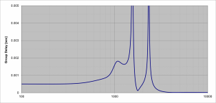
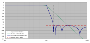
For example I have attached two plots, one of the lowpass filter response and the other of the filter's group delay. If you look at the GD, it's flat until about 500 Hz where it turns up slightly and then more sharply at 900Hz but the peaking is not bad. Above 1kHz the filter has entered the transiton band and the response is falling, and you can ignore the features above 1.5k Hz. The response gives about 48 dB of attenuation but the requirement for what we are doing is much less severe than for normal antialiasing because the sidechains producing the harmonics will be mixed back at much reduced levels. There are steeper and deeper filters that I can use but in trade they have higher peaking near Fc and higher passband delay. It might be possibly to offer a few different ones or I might just try to find a good compromise and then just go with that.
The filter is not a brick wall and does not reach the stopband until 1.5 times the corner frequency. Since it is the stopband edge that must correspond to the Nyquist frequency there is a partial octave that is occuring in the transition band that would be passed by a brick wall filter. This will happen to some degree (depending on the width of the transition band) for any non brickwall filter. But the result should be just fine.
So IIR is really the best option here IMO, unless someone can change my mind.
You said:
That's not really a good characterization of the group delay profile. When the passband ripple is low the group delay in most of the passband is flat. This means linear phase in the passband, just like the vaunted FIR stuff. The difference comes as you approach the corner frequency. In this region the delay grows and has a peak around Fc. This is "group delay peaking". One has to be careful in designing the filter so that this is not too severe. But I have experience in doing this.With IIRs you'd have to pick between lagging the HF with respect to the input, leading the LF, or some balance between the two.
For example I have attached two plots, one of the lowpass filter response and the other of the filter's group delay. If you look at the GD, it's flat until about 500 Hz where it turns up slightly and then more sharply at 900Hz but the peaking is not bad. Above 1kHz the filter has entered the transiton band and the response is falling, and you can ignore the features above 1.5k Hz. The response gives about 48 dB of attenuation but the requirement for what we are doing is much less severe than for normal antialiasing because the sidechains producing the harmonics will be mixed back at much reduced levels. There are steeper and deeper filters that I can use but in trade they have higher peaking near Fc and higher passband delay. It might be possibly to offer a few different ones or I might just try to find a good compromise and then just go with that.
The filter is not a brick wall and does not reach the stopband until 1.5 times the corner frequency. Since it is the stopband edge that must correspond to the Nyquist frequency there is a partial octave that is occuring in the transition band that would be passed by a brick wall filter. This will happen to some degree (depending on the width of the transition band) for any non brickwall filter. But the result should be just fine.
Attachments

Last edited:
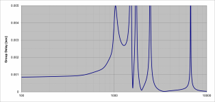
Here is an example of a steeper filter. Again the stopband is at 1.5 times the corner frequency but we have 86dB of attenuation there. Note the higher peak in the plot of group delay neat Fc (1k Hz). It's difficult to say if this would be audible if the levels of distortion products are only a few percent, that is only a couple percent of the sidechains are being re-combined with the fundamental.
Attachments
I was trying to suggest that you could compensate (relatively) for the laging HF phase of the filter by delaying the unprocessed signal before summing. This would mean the processed signal would have (relatively) some phase lead in the LF. That said, if it were me, I'd take the HF phase lag that comes with the simplest implementation over introducing more complexity.That's not really a good characterization of the group delay profile.
I know effectively nothing about implementing LADSPA plugins, including their computational constraints, so I'm really looking forward to seeing where you take this.
This sounds way too complicated.
I would start by creating a working system first, something like:
Sampled input --> lookup table --> modified output. Now if only I could find a working Ladspa host that actually builds without failing on some stupid dependency that nobody else uses (and requires the latest nightly build for no reason), or, better still, is packaged by Fedora because it actually works... (sigh)
Then I would try to figure out a way to transform a sine wave into a diagonal straight line. And use that as the basis for creating lookup tables.
@abstract At first this was the idea I was planning to run with. It seems very simple! You have an in-out relationship that is just a straight line in the case of no modification of the signal (no added distortion). Then it is just a matter of defining that relationship via a LUT or analytic function such that distortion is introduced. But there is a big problem: the curve will generate distortion products that are higher in frequency, meaning above the Nyquist frequency, and they will be aliased back down below that.
Now it is possible to use an anti-aliasing filter to remove part of the signal that would produce the "too high" distortion products, but that would also get rid of much of the audio band in this situation because you are just processing the audio directly into the distorted audio signal.
Instead, by generating distortion at some controlled level and for only one harmonic at a time each in their own sidechain, you can customize the AA filters for each sidechain and leave the fundamental completely untouched. So that is the way I am planning the design.
So the input is analogue? If we're already dealing with a sample stream, then we can simply modify the amplitude of each sample without resampling time-wise. So if the input is sampled at 44.1k, nothing above 22.05kHz can be generated from post-processing those samples.
Amplitude-wise could be another matter, if we have, say 16 bits of resolution, a 65k by 65k lookup table would have a curve quantized to the nearest sample, which might not be very accurate. Probably ok for proof-of-concept, but not as intermediate values for further processing like interpolating multiple samples.
Amplitude-wise could be another matter, if we have, say 16 bits of resolution, a 65k by 65k lookup table would have a curve quantized to the nearest sample, which might not be very accurate. Probably ok for proof-of-concept, but not as intermediate values for further processing like interpolating multiple samples.
@abstract From what I understand you are wrong about that.
See this page, especially plot at top right.
https://www.fieldingdsp.com/alias
Also:
https://varietyofsound.wordpress.com/2011/10/05/myths-and-facts-about-aliasing/
See this page, especially plot at top right.
https://www.fieldingdsp.com/alias
Also:
https://varietyofsound.wordpress.com/2011/10/05/myths-and-facts-about-aliasing/
Last edited:
- Home
- Source & Line
- PC Based
- checking interest: LADSPA plugin for generating euphonic or other distortion