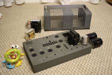
I've been working, very slowly on a project to build a DIY version of the Mr. Millet's Wheatfield HA-2. I'm trying to be cheap as far as the chassis and power transformers are concerned. Cross fingers.
So far I've been cleaning out an old Bogen PA chassis that I'd like to use for this. It's already got octal sockets and a choke so that's less drilling. I've also got a Triad C-14X (6H 120ohm 200ma) choke to use as an alternate, but the ancient choke on the chassis looks pretty beefy and reports as about 80ohms instead, so I'll give it a whirl.
I'm concerned that my power supply may be too small. It's an Allied Electronics 6K56VG (540vct, 120ma) whereas I just discovered to day that the Wheatfield can use a Hammond 270HX which is rated for 200ma. I'm curious how much the 6SN7/6AS7 setup can draw. I figure as long as the current rating is OK I can use a 5AR4 instead of the 5U4GB to get the voltage up, or worst case I can use hexafreds to minimize the voltage drop.
Anyway, HERE a thread discussing the same topic. I just didn't want to dig up an old thread:
Another thing that has caught me off guard are the Solen 100uF 400v caps I bought for this. They're enormous and won't fit in the chassis, So I figure I'll have to zip-tie the big boys to the top of the chassis and of course insulate the leads appropriately.
I've salvaged some nice terminal strips from a couple of Tektronics oscilloscope modules that will be handy if they fit in the chassis.
So now I just need to figure out a good layout and then do a bit of drilling.
Stay tuned! Pics to follow.
I'm concerned that my power supply may be too small. It's an Allied Electronics 6K56VG (540vct, 120ma) whereas I just discovered to day that the Wheatfield can use a Hammond 270HX which is rated for 200ma. I'm curious how much the 6SN7/6AS7 setup can draw. I figure as long as the current rating is OK I can use a 5AR4 instead of the 5U4GB to get the voltage up, or worst case I can use hexafreds to minimize the voltage drop.
Use SS rectification and a CLC filter. Use as small a cap. as you can in the 1st position, consistent with an appropriate B+ rail voltage. More current can be drawn from the power trafo, when the rectifier conduction angle is large. The smaller the 1st cap., the larger the conduction angle.
I suggest you use a "cockeyed bridge" for rectification. It should cost less than FREDs, while blocking SS diode switching noise from entering the PSU filter. Assemble 2 sets of series connected UF4007 pairs. Snub each diode pair with a HIGH WVDC 10 nF. capacitor. Connect the cathode end of the assemblies to the rectifier winding's ends. Ground the anode end of the assemblies. Connect the anode of a 600 PIV Schottky diode to the rectifier winding's CT. Take the "raw" B+ from the Schottky's cathode. By itself, the Schottky diode's speed keeps PN junction diode switching noise out of the PSU filter. The UF4007 assemblies are snubbed to keep switching noise out of the power trafo, where it could get into the tubed circuitry via the heater supply.
Excellent advice! A light bulb went off in my head along with your suggestion, where I've got another amp that makes some switching noise from it's pair of UF4007's.
How much variation can I use with the 10nF snubber? I've got a 47nF 2000vdc handy, and a couple 47nF 600vdc orange drops available.
I've already got a spare pair of IXYS DSEI12-12A FRED's. Should they be quiet enough? I was planning to use the center tap of the power transformer along with the FREDs. Can that be snubberized? I do have a mess of UF4007's too so the bridge is no problem.
I have a serious soft spot for Mr. Millett's work. In fact, I'm such a fan that Pete and I cooked up a design called "The Menace" which is essentially the opposite of what you're working on. It's a modified/redesigned HA-2 with the bulk of the mods comprising a completely new power supply design and adding a second, parallel output tube.
Here's some eye candy to keep you inspired on your current build.
Power Supply

Amp Section

Amp Upskirt

And if you're still looking for a power transformer I have a 270HX that I pulled off of my old HA-2 (I modified it to use a 370HX before selling it) that I could pass along very cheaply. As far as just how much current this amp draws it's almost entirely dominated about the 6AS7 output tube and controlled by the cathode resistor (R15 on the original schematic). Make sure you have that resistor adequately sized and ventilated. A cool running amp this is not.
[edit]I just caught the part in your original post about your power trafo being rated for 120mA, that's nowhere near enough if you build the amp according to the original schematic. Current draw for the original amp is up around 180mA and if you adjust the cathode resistor to lower the current on the output tube to make your power supply work you'll affect the performance of the amp significantly.
Here's some eye candy to keep you inspired on your current build.
Power Supply
Amp Section
Amp Upskirt
And if you're still looking for a power transformer I have a 270HX that I pulled off of my old HA-2 (I modified it to use a 370HX before selling it) that I could pass along very cheaply. As far as just how much current this amp draws it's almost entirely dominated about the 6AS7 output tube and controlled by the cathode resistor (R15 on the original schematic). Make sure you have that resistor adequately sized and ventilated. A cool running amp this is not.
[edit]I just caught the part in your original post about your power trafo being rated for 120mA, that's nowhere near enough if you build the amp according to the original schematic. Current draw for the original amp is up around 180mA and if you adjust the cathode resistor to lower the current on the output tube to make your power supply work you'll affect the performance of the amp significantly.
I've already got a spare pair of IXYS DSEI12-12A FRED's. Should they be quiet enough?
Use the FREDs (unsnubbed) as the connections to ground of a "cockeyed" bridge. The Schottky on the CT keeps crud out of the B+ rail. By themselves, FREDs are pretty quiet (better than unsnubbed UFnnnn) and I don't know what (if anything) works to snub them. Take no prisoners and put ferrite beads on the heater wiring as close to the power trafo as can be.
I'm glad I piped up. 180ma wow. 
n_maher That's one heck of a power supply! Thats a lot of transformers! And thanks for the generous offer! I've read that paralleling the 6as7's allows helps with low impedance phones.
Eli thanks for the tips!
It appears the power transformer I've got won't cut it. I'll run some calculations to determine if a 270HX and the Triad choke will work out with solid state rectification. I've got a ton of 5U4's but they're hit-or-miss so I may go with Eli's suggestions there.
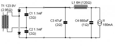
For the ps, I was going to follow the schematic fairly closely:
47uF --> 6H 120ohm --> 47k ohm bleeder to ground --> 3 x 220uF
For the cathode resistor I've got the heavy duty aluminum resistors that n_maher appears to be using too. I've salvaged a couple heat sinks with nice copper heat spreaders on them . I've also got a huge aluminum heat sink that I'm going to pull from a toasted PA amp that I could attach the resistors to.
180ma wow.
n_maher That's one heck of a power supply! Thats a lot of transformers! And thanks for the generous offer! I've read that paralleling the 6as7's allows helps with low impedance phones.
Eli thanks for the tips!
It appears the power transformer I've got won't cut it. I'll run some calculations to determine if a 270HX and the Triad choke will work out with solid state rectification. I've got a ton of 5U4's but they're hit-or-miss so I may go with Eli's suggestions there.
For the ps, I was going to follow the schematic fairly closely:
47uF --> 6H 120ohm --> 47k ohm bleeder to ground --> 3 x 220uF
For the cathode resistor I've got the heavy duty aluminum resistors that n_maher appears to be using too. I've salvaged a couple heat sinks with nice copper heat spreaders on them . I've also got a huge aluminum heat sink that I'm going to pull from a toasted PA amp that I could attach the resistors to.
180ma wow.
WLR,
At 2.5 A./6AS7 heater, your going to need a hefty filament trafo, especially if you use 2X PSE sets for the "finals".
There is another way to get the B+ current you need, in an economical manner. Follow in the footsteps of "El Cheapo". Buy a Triad N-77U and a Triad VPL16-1600. Phase the 3 secondaries up and wire them in series. Use the composite to energize a Greinacher ("full wave") voltage doubler consisting of your FREDs and 2X 250 WVDC/820 μF. 'lytics. Of course, inrush current limiting via NTC thermistor(s) is a must.
BTW, if you don't already have a suitable 'SN7, consider the Loctal 'F7.
Try coping with the 360mA+ that the Menace draws.whitelabrat said:I'm glad I piped up. 180ma wow.

It's not exactly portable, that's for sure. And actually, what you're seeing is a single transformer and 3 chokes with caps scattered about for good measure. I think it weighs about 40lbs or so.n_maher That's one heck of a power supply! Thats a lot of transformers! And thanks for the generous offer! I've read that paralleling the 6as7's allows helps with low impedance phones.
And no worries if you don't end up wanting the 270HX, I've been mulling over building another HA-2. I have almost enough spare parts to do it and tubes coming out of my ears for this amp.
 It's a sickness...
And Eli has hit the mother load with his loctal advice, the 7N7's are cheap and better then an awful lot of the 6SN7s you'll find. I built an adapter for mine so that I can run some of the boutique 6NS7 variants that I have but also have the option to run 7N7s as well.
I do have two Oneac isolation transformers, one is rated for 1A and another for 2A. A voltage doubler should give me just about 300vdc using the 1A transformer. It shouldn't buzz like the Hammond either.
I may be able to use the 6K56VG to make an EL Cheapo variant for the pile of 6aq5's so not all is lost. Radshac sells a 3A 12.6vct transformer real cheap too.
I've got five or six 6SN7's so I'm good to go there.
I may be able to use the 6K56VG to make an EL Cheapo variant for the pile of 6aq5's so not all is lost. Radshac sells a 3A 12.6vct transformer real cheap too.
I've got five or six 6SN7's so I'm good to go there.
I may be able to use the 6K56VG to make an EL Cheapo variant for the pile of 6aq5's so not all is lost.
120 mA. is not enough for an "El Cheapo". The 4 'AQ5s draw that much "sitting at idle". You might be able to get a suitable B+ rail out of the 6K56VG, by phasing up the 2 filament windings in series and using the composite, in the boost configuration, on the primary side. SS rectify and cLC filter the CT secondary. A substantial amount of inductance is needed to hold ripple down. The Hammond 193J is a safe choice.
Try coping with the 360mA+ that the Menace draws.
The $69 AnTek AN-62115 will loaf on that job. Wire the secondaries in series and bridge rectify. Pseudo-separate supplies could be done with a pair of Greinacher voltage doublers.
Eli Duttman said:
The $69 AnTek AN-62115 will loaf on that job. Wire the secondaries in series and bridge rectify. Pseudo-separate supplies could be done with a pair of Greinacher voltage doublers.
There are always individual bits that will work better than a conglomerate like the BFT-1B but I liked the ease of one stop shopping that it offered and the overall simplicity of the PS that resulted. It had every secondary voltage and capacity I needed in a pretty tidy footprint.
So here's what I think I can do for the PS. I'm going to leave the PS outside of the chassis, where I've got a medical grade twist lock plug and socket that I can use to keep anyone from accidently plugging the amp into mains.
For the voltage doubler I'll use four 2200uF 100v, two wired in seiries to get up the voltage rating which should be good for 1100uF 200v. I was going to use these for something else, but this comes first. If the voltage is too high, I can use 120uF 450v caps instead.
The rest is by the book. If the voltage is too high I can use the smaller 1A isolation transformer.
I'll also need to find a way to cram a power switch and a soft start circuit into the oneac's little chassis.
Attachments
Using the above config the heater transformer will have it's own connection to the mains. I figure I should also mount a DPST switch, one side for the heater transformer's primay and one side for the B+ secondary, just to be sure I don't accidently turn on the B+ without the heaters running.
Phil,
I've sent you two emails back now, one yesterday, one today. Not sure if you aren't getting them but check your spam folder and make sure I'm not getting blocked.
I've sent you two emails back now, one yesterday, one today. Not sure if you aren't getting them but check your spam folder and make sure I'm not getting blocked.
Phil,
IMO, C3 in your PSU schematic is going to buy you very little. Given the tiny conduction angle associated with those huge caps. in the doubler stack, it is inevitable that LOTS of "hash" is going to be present. I suggest you replace C3 with a LC section made up of a 6.8 mH. RF choke (Mouser stock # 542-5900-682-RC) and a 1500 pF. cap. of either mica or NPO ceramic construction.
Kill the worst of the "hash" off before it reaches the main filter choke whose internal capacitance acts as a short circuit to RF energy.
Don't forget to protect both the power trafo and the tubes by adding inrush current limiting to the B+ PSU.
whitelabrat,
though I'm no expert I dare to chime in...
apart from what Eli says I would resim your psu arrangement with more realistic values, like for transformer resistance and the first two caps in the doubler. Will not make a very big difference but depending from what transformer you are going to use your results might be off...
I built a two-toroid psu with a voltage doubler myself for my Aikido headphone amp and I can't comment on conduction angles ('cause I don't have a clue to be honest), but I am using a mains filter right after the IEC socket. 😉 From all the headphone amps I built this one to my ears has the 'blackest background' sonically.
Coming back to the topic of this thread I also am kinda interested in the HA2 for quite some time and actually have gathered most of the parts except for the iron. I also went at the schematic and did some changes that can be seen in the attached schematic. Any comments on this are very welcome though I hope this doesn't qualify as threadjacking 😱
About the current draw of the original HA2.... are those 180mA real?
Sort of reverse simulating the original Wheatfield psu in PSUD2 doesn't give me nowhere near 300V...? So far all the psu's I built were basically spot on to the simulation, so that leaves me puzzled.

Stixx,
I'm pretty confident in the 300V number but just to be sure I'll shoot Pete and email and see if I can't get him to chime in in this thread. FWIW the PS for my HA-2 variant runs ~@270V on the B+ depending on the rectifier used. I never measured B+ on the Wheatfield when I had it.
I'm pretty confident in the 300V number but just to be sure I'll shoot Pete and email and see if I can't get him to chime in in this thread. FWIW the PS for my HA-2 variant runs ~@270V on the B+ depending on the rectifier used. I never measured B+ on the Wheatfield when I had it.
I can't comment on conduction angles ('cause I don't have a clue to be honest)
In a cap. I/P filtered PSU, current flows in the rectifying diodes only a small portion of the 360o sine wave. That's the conduction angle. As the I/P capacitance increases, the charging pulses get shorter, while increasing in current.
All cap. I/P filters exhibit a "triangular" ripple wave form. As I/P capacitance increases, that wave form becomes more and more "sharp". The Fourier theorem tells us that "sharp" periodic wave forms contain considerable high order overtone components.
The HUGE capacitance Phil intends to use will crush the ripple fundamental, but very considerable overtone energy (well into RF territory) will be present. The LC section of a RF choke and small cap. I suggested "dulls" the ripple waveform down to the point that the main inductor and reservoir cap. can finish the job off. The background will be very black, indeed. 🙂
BTW, ferrite beads on the primary side of the doubler trafo suppress the propagation of "hash" in to or out of the PSU.
- Status
- Not open for further replies.
- Home
- Amplifiers
- Tubes / Valves
- Cheapfield project