If I recall correctly what you're probably hearing isn't heater hum but rather some power supply ripple. The way to test this (again, I'm relaying info here) is to use something like a 5998 in the output which helps increase PSRR. I know that worked for my HA-2 so you might give it a shot.
5998? But I've got something like a triple lifetime supply of 6AS7/6080's. I was going to do a Futterman power amp, but I'm more interested in headphones now. I'm surprised that there would be that much ripple even after so much ps filtering.
So I've got three 600uF ASC caps, three 120uF electrolytics, a 33uF electrolytic, and two chokes that I could use to add even more smoothing. Any suggestions folks? If I do have to use another choke I would guess that I'd have to move to hexafred rectifiers to keep the voltage up.
So I've got three 600uF ASC caps, three 120uF electrolytics, a 33uF electrolytic, and two chokes that I could use to add even more smoothing. Any suggestions folks? If I do have to use another choke I would guess that I'd have to move to hexafred rectifiers to keep the voltage up.
Yeah, 5998s which lately seem to have been getting a bit scarce. Part of the reason that I built the Menace was to give the HA-2 a better PS. And B+ could drop a bit and I think you'd still be fine. You could also switch to a 5AR4 which would help you pick back up some of the B+ lost to add'l filtering (I think).
So I've got three 600uF ASC caps, three 120uF electrolytics, a 33uF electrolytic, and two chokes that I could use to add even more smoothing. Any suggestions folks?
Yes, pull the smaller of the 2 chokes in situ. Replace that genuine inductance with a gyrator. A gyrator will allow you to "synthesize" a GARGANTUAN inductance and stamp ripple out. Between reduced resistive losses and switching to 5AR4 rectification (as previously suggested) the Volts needed to operate the gyrator should be available.
Yes, pull the smaller of the 2 chokes in situ. Replace that genuine inductance with a gyrator. A gyrator will allow you to "synthesize" a GARGANTUAN inductance and stamp ripple out. Between reduced resistive losses and switching to 5AR4 rectification (as previously suggested) the Volts needed to operate the gyrator should be available.
Has anyone here actually tried and built a gyrator? Looks very simple (and is easy to read for me since it's in german) and easy to implement...
Looks like I'm the guinea pig. 🙂
It seems like whenever I order parts (after building a parts list) there's always just one more thing that I shoulda gotten. Looks like I can find all the parts no problem and it should be good up to 500v.
Mine Deutch ist nicht so gut. I think I get the idea though. Big Inductance.
I've also been turned onto TIP50's as capacitor boosters, but that's for another day.
I've taken it upon myself to catalogue at least my collection of resistors. I won't let myself place any orders until I get that done. I'm kicking myself for recently buying certain values when I had hundreds of some vales hiding in a box. 20k, 1.5k, 1k, etc. I just didn't know what was in there. I've already got one of the two required resistors for the Gyrator. 53 values down... many more to go.
I've got 17V Zeners comming out of my ears!
I've got 17V Zeners comming out of my ears!
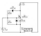
I've got all the parts for the Gyrator. A couple translated points. X1-1 is the input or the + side, and the X1-2 is the output, or negative. It would also appear that increasing the value of C1 also increases inductance.
There are some things about the Gyrator schematic that Ist nicht klar.
What voltages can I expect on C1. I got a 4.7uF rated for 450v just to be safe, but I also suspect that the voltage shouldn't go much past 15v there right? I've also got a 10w resistor for the 33 ohm where I figure that's where most of the juice will be flowing. I just happen to have two 5w 330k resistors, which may be overkill so I could possibly mix and match a couple 1/4 w resistors if possible to get 330k. I figure I'll stick with overkill while dealing with the unknown.
I'll have to improvise a heat sink for the IRF840. I've got plenty from salvage. I would expect some dangerous voltages on the tab.
On a side note, I'm glad I ended up using the enormous heat sink for the cathode resistors. After an hour of operation the heat sink got very warm, almost uncomfortable, despite the chilly condition of my basement.
I suppose the last photo was a bit too tight. It hangs of the back and is fully exposed like the 1st photo (pile of parts) suggests. One I find a bottom plate and some feet I should have more of a chimney effect with the heatsink.
One other thing that I noticed is that there are a couple of areas where you have heater wires running parallel and in close proximity with signal wiring. You might try to reroute signal wires away from the heaters if possible, I've always been told to only have them cross at right angles (again, if possible) and if not you might also try using shielded wire.
During testing the output signal was going through alligator clips that were bumping up right against the heaters. Before I insert the Gyrator, I want to be sure that isn't the source of the hum. In the end those wires will be shielded just like the input signal from the RCA jacks to the attenuator.
Good point about the heater's and signals. The 3d-ness of the photo isn't very good. The little red resistors are the 100 ohm resistors that carry the signal. There are the black wires that run under the terminal strips to the 100 ohm resistor that goes to the 6AS7. That may be a good one to use with shielded wiring. The white shielded wire is some sort of mil-spec surplus, with Teflon internal insulation, and braided silver (plated?) shielding on the outside. I don't know what it's voltage rating is though, which is why I didn't use it there. Without measuring I wouldn't expect there to be more than 180v on those wires, but that may spike during power on. The black wire is good to 600v.
Good point about the heater's and signals. The 3d-ness of the photo isn't very good. The little red resistors are the 100 ohm resistors that carry the signal. There are the black wires that run under the terminal strips to the 100 ohm resistor that goes to the 6AS7. That may be a good one to use with shielded wiring. The white shielded wire is some sort of mil-spec surplus, with Teflon internal insulation, and braided silver (plated?) shielding on the outside. I don't know what it's voltage rating is though, which is why I didn't use it there. Without measuring I wouldn't expect there to be more than 180v on those wires, but that may spike during power on. The black wire is good to 600v.
I was playing with some power supply variations using PSU Designer II. It would seem that the 40uf (2 x 20uF) --> 6H 120ohm --> 660uF (3 x 220uF) --> 180ma CCS does indeed leave some ripple according to the simulations. I tried it again by upping things from 660uF to 1260uF (660 + 600). No more ripple. Should be an easy test.
Due to icy weather I get to work from home today. So to entertain myself I've got the amp wired up, but this time I've got the two ASC caps as output, and one in the power supply. Less hum and bass seems tighter. But there is some hum. And it comes from one channel more than the other. So I don't think it was the power supply as much as exposure to the heater wiring.
I also attached the jumper cable that was bumping up against the heater wire to the cathode resistor instead of the tube socket, which may have something to do with the reduction in hum. I think I'll try Nate's suggestions to try to improve that a bit more.
The ASC's may become permanent since this amp will only live at home. I'll need to keep the ASC's in a sub-chassis that will live under the main chassis. Right now a cardboard box is doing the job. They sound surprisingly good for caps that should be in refrigerators or something. That or I'm going deaf from all the gigging when I was younger. 😀
Also, I've got the amp attached to a Kill-A-Watt. It draws 120 watts! Won't be running this on a 9v battery anytime soon.
I'm still curious about the Gyrator though. Stay tuned.
The ASC's make excellent output caps in my experience.
As far as the residual hum is concerned I wonder if you couldn't get some valuable information if you had access to either a scope or run the amp through the RMAA tests? I recently bought a scope and if I can bring myself to lug the 60lb beast down into my lab my intention is to see what sort of ripple I have in the power supply. I've also started work on a switchable dummy load so that I can run the amp through the gamut of RMAA tests and see how it performs.
In other news I've spoken with a commercial amp manufacturer who's spent some time playing around with this circuit (not Pete). In his experiments what ultimately made the difference was DC filament supplies. I'm not sure I'm willing to go there just yet as it would involve some pretty major surgery in my amp. But we'll see once I've been able to do some exploring.
This schematic may be worth a look. I don't think I'd do a regulated supply though. I would figure that even with a lot of ripple it would still be quieter than AC.
I think it's odd that I'm getting more hum on one channel than the other. Hmmmm.
Anyone ever try wrapping the heater wires in foil and then grounding that?
I think it's odd that I'm getting more hum on one channel than the other. Hmmmm.
Anyone ever try wrapping the heater wires in foil and then grounding that?
I just thought of something. As in the schematic I have a 10ohm 1w resistor attached to each of the heater wires. That 10ohm resistor attaches to a ground bus that is also used by... tada... the left channel, where the greater amount of hum comes from. The only reason I could understand for keeping these 10ohm resistors around is to drag down the voltage a bit by making a bit of a load.
So I'm thinking removing those 10ohm guys may help. I could see attaching them to the 6.3v center tap, but it appears the ct has been removed from the power transformer. I'll also need to keep an eye on the heater voltage. If I need to drop it, I can use some very low value resistors in series with the heater wiring to get the volts down.
So I'm thinking removing those 10ohm guys may help. I could see attaching them to the 6.3v center tap, but it appears the ct has been removed from the power transformer. I'll also need to keep an eye on the heater voltage. If I need to drop it, I can use some very low value resistors in series with the heater wiring to get the volts down.
Whitelabrat,
Have you built the gyrator yet? I'm going tod do the same but for lower voltages and to drop 72V DC to about 60V for use in a 150W SS amp. I'm interested in your experience - I'll be using the same circuit but possibly putting a zener in there to regulate the V out.
Have you built the gyrator yet? I'm going tod do the same but for lower voltages and to drop 72V DC to about 60V for use in a 150W SS amp. I'm interested in your experience - I'll be using the same circuit but possibly putting a zener in there to regulate the V out.
Attachments
I've got all the parts, for a gyrator, but I haven't gotten around to putting something together yet. I want to be able to prove that it really works, so I've been trying to resurrect my Tek 531 so I have some sort of proof. It turns out that the 53/54C plugin doesn't seem to like the 531 oscilloscope and I parted out the two other plugins that I had that probably would have worked.
On another note, I tried wrapping the heaters in tin foil and then soldered a wire to the ground. That didn't seem to make any difference. I'm going to remove the ferrite block from the heater as a start, but I'm beginning to believe that DC heaters are the way to go. At least for the output tube. I may do a sort of hybrid, where the 6SN7 remains AC because I don't trust DC heaters for tube life.
I think the easiest solution would be to hunt down a 9v 4A switching power supply and just go with that. Time for some dumpster diving.
- Status
- Not open for further replies.
- Home
- Amplifiers
- Tubes / Valves
- Cheapfield project