In a cap. I/P filtered PSU, current flows in the rectifying diodes only a small portion of the 360o sine wave. That's the conduction angle. As the I/P capacitance increases, the charging pulses get shorter, while increasing in current. All cap. I/P filters exhibit a "triangular" ripple wave form. As I/P capacitance increases, that wave form becomes more and more "sharp". The Fourier theorem tells us that "sharp" periodic wave forms contain considerable high order overtone components. The HUGE capacitance Phil intends to use will crush the ripple fundamental, but very considerable overtone energy (well into RF territory) will be present. The LC section of a RF choke and small cap. I suggested "dulls" the ripple waveform down to the point that the main inductor and reservoir cap. can finish the job off. The background will be very black, indeed. BTW, ferrite beads on the primary side of the doubler trafo suppress the propagation of "hash" in to or out of the PSU.
Eli, thank you for the explanation! I might even try the suggested LC section in my Aikido psu sometime in the future...
Nate was kind enough to sell his Hammond 270HX to me so I think I'll stick with a design that focuses on those constraints. I'm intrigued with all the ps design concepts here.
I was looking to use the huge caps only because I've got a pile of them. I can use them for another project.
So here's what I've collected for the ps:
Lots of 5U4GB's
2 FRED's
Three 220uF 450v caps
Two 120uF 450v caps (optional)
Two 47uF 450v caps
6H 120ohm choke (could swap with a 5H, 65 ohms but would rather not if possible)
Two 10uF Film caps
Six 2200uF 100v caps
Four 330uF 100v caps
I've got a lot of UF4007's and all sorts of small value capacitors.
I used to do FCC certification back in the 90's so I've developed the habit of saving all the ferrite blocks off things before they hit the dumpster. I'm set there.
For all practical purposes the isolation transformer approach would be cheapest. Especially since you can often pick them up cheap on the 'bay.
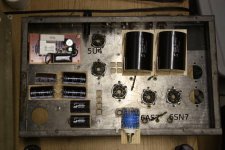
I did some cleanup on the chassis this weekend. What a mess. I think it may be worth chipping in to replace the old crusty tube sockets. To Deoxit or not to Deoxit?
Thanks again to n_maher. I suppose a small % of my amp will be a real HA-2 huh? Interestingly the 270HX is just about the same size as the 6K56VG.
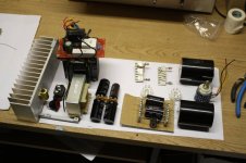
I'm still pondering layout. I've got an enormous 8 X 4 X 2 heat sink that I'd like to use for the 6080 cathode resistors. Way overkill, but it's awesome and I have to use it for something.
I may just kinda wing it. There's not a lot of parts. They're just bulky. I figure I'll just layer my way up. So here's the plan:
Mount the big iron and most hardware.
Mount Heatsink.
Mount terminal strips.
Wire in the heaters, B+, and grounding.
Capacitors.
Resistors.
Finish any remaining bits.
Thanks again to n_maher. I suppose a small % of my amp will be a real HA-2 huh? Interestingly the 270HX is just about the same size as the 6K56VG.
I'm still pondering layout. I've got an enormous 8 X 4 X 2 heat sink that I'd like to use for the 6080 cathode resistors. Way overkill, but it's awesome and I have to use it for something.
I may just kinda wing it. There's not a lot of parts. They're just bulky. I figure I'll just layer my way up. So here's the plan:
Mount the big iron and most hardware.
Mount Heatsink.
Mount terminal strips.
Wire in the heaters, B+, and grounding.
Capacitors.
Resistors.
Finish any remaining bits.
Attachments
Sweet, glad to see this progressing.
And sorry for forgetting to toss the free tubes in the box with the trafo, life has been nuts for the past few weeks.
About the cathode resistors, I'd run as big a heatsink as you can on them as they really do run quite hot. You can see in my earlier pictures that I added external resistors to my build to help dissipate the hot spot that formed above the resistors. Even with those I'd guess operating temp to be ~150F.
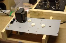
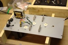
I stared and stared at the old Bogen chassis and came to the conclusion that it wasn't worth trying to shoehorn everything in there. So I'm ordering a cheap 16 x 8 steel plate to mount everything on along with three sockets. I've made a paper template so I have a guide for cutting holes into the plate. I'm much happier with this layout. The sides of the chassis will be pine for now, which will make a nice little cave for all the parts to fit in.
The terminal strips will have most of the circuit on them. One side will be hot and the opposing strip will be grounded.
The circuit board sitting on the power transformer is a Chinese soft start circuit that I bought for another project but never used. The heat sink is large enough to be the back end of the chassis.
Attachments
You might want to rethink the stepped attenuator. This amp has a lot of gain and may prove problematic depending on what you're driving with it and what the output of your source is. Otherwise looking good!
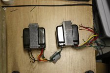
n_maher, question for you. I notice that on the photos of your super-HA2 you use big can film capacitors on what I would guess are the outputs? What values / materials are those?
I'm curious where I just picked up three huge 600uF cans for dirt and I'm wondering about their suitability for audio signals.
I also don't expect the attenuator to provide a mute ability, but perhaps you know of other problems it may introduce?
I've been drilling, and drilling and should be able to begin assembling soon. I'm debating if I should paint the grey plate everything is being mounted on or if I should leave it alone. It's a bit cold outdoors, but I could fire up a 40,000 btu radiant heater to warm things up while I paint.
Each output on that amp has 2 x 100uf/400Vish motor-run film caps. A good friend recommended using them as output coupling caps and so far I agree.whitelabrat said:n_maher, question for you. I notice that on the photos of your super-HA2 you use big can film capacitors on what I would guess are the outputs? What values / materials are those?
Can't hurt to try and that's certainly enough capacitance to avoid frequency response issues. 🙂I'm curious where I just picked up three huge 600uF cans for dirt and I'm wondering about their suitability for audio signals.
The HA-2 has quite a bit of gain so you may find that the steps really limit the amount of fine tuning you can do with the attenuator. I've become increasingly frustrated with 24 step attenuators over the years and flat out just won't use them any more. If I had just one source it might be more possible to gain match my entire rig but I'm all over the map in that respect so I need my amps to be very flexible. YMMVI also don't expect the attenuator to provide a mute ability, but perhaps you know of other problems it may introduce?
Can't wait to see the pictures!I've been drilling, and drilling and should be able to begin assembling soon.
The kind folks at ASC were able to send me a datasheet about the GLY513. Non-inductive metallized polypropylene. These should be excellent.
They guy who sold 'em to me on ebay appears to have a couple more if anyone is interested. Just look for "ASC 600 mfd"
I got the 100uF Solens for the job, but now I'm curious about the ASC's if they can fit on top. It would make for one lumpy looking amp!
The Solens have a lower resistance though at 0.001 ohm where the ASC has 0.006 ohm. In either case, better than electrolytics.
One thing, in the schematic Millet calls for a 20W cathode resistor. Maybe a mistake?
It dissipates 18 Watts!!!
It dissipates 18 Watts!!!
That's right about the cathode resistor. I'm going to use a pair of 25w resistors. It's also necessary to attach them to some sort of with some heat sink grease.
Mr. Rat,
Would you mind sending me the datasheet for those ASC caps.? My order came today and I'm curious to find out exactly what I got. 🙂 Price was too good to pass up even if applications are limited.
Thanks!
Would you mind sending me the datasheet for those ASC caps.? My order came today and I'm curious to find out exactly what I got. 🙂 Price was too good to pass up even if applications are limited.
Thanks!
Check your e-mail.
I figure I'll test the amp with the ASC and the Solen caps before I commit any holes to the metal chassis. Just need to find 3" capacitor clamps in case I use the ASC's.
I figure I'll test the amp with the ASC and the Solen caps before I commit any holes to the metal chassis. Just need to find 3" capacitor clamps in case I use the ASC's.
whitelabrat said:Check your e-mail.
I figure I'll test the amp with the ASC and the Solen caps before I commit any holes to the metal chassis. Just need to find 3" capacitor clamps in case I use the ASC's.
Try and find clamps with 3 mounting screws. I've used the 2-screw type on some simliar sized caps and they work, but not great. Surplus Sales appears to have some that would work for a decent price.
And thanks, email received. 🙂
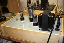
Good news. I was able to steal away enough free time over the holidays, especially today and I was able to do a smoke test.
Holy Shitake Mushrooms! This amp rocks. I was stunned that the amp worked on the first try. And then that it sounds better than anything I've ever heard. The ER4S headphones are normally a bit dry, but after putting on T.I.'s Paper Trail I though I was in one of the souped up Hondas that go bass'n down my street. Charlotte Church's performance of Ding Dong! Merrily We Go. gave me goose pimples.
I tried both the ASC and Solen output coupling caps. I don't know if I can tell the difference. I'll have to try again later. I'll probably use the Solens either way. The $5 ASC's are worth a look though, vs the $35 Solens.
The heatsink is undoubtedly overkill. It gets warm, but not hot.
Happy New Year!
Attachments
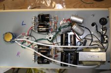
Here's a shot of the almost completed undersides. I'm not gonna win any awards for my point-to-point work.
I should also mention that I've decided to use a 5AR4 rectifier instead of the 5U4GB. With the 5AR4 the B+ sits at about 296v which is just about on target.
I was going to use a single 47uF cap before the choke, but I began to get nervous about that. It was either that or a 33uF. Turns out I had some unused Mallory 20uF 450v cap laying about so I paralleled them for 40uF. So the 47uF just ended up doing work on the other side of the choke.
I do have a bit of heater hum. I may have some tweaks to help that some. What I don't understand is why have the heater primaries grounded with 10 ohm resistors? I sent those to the star ground, but it just doesn't make sense to me.
Attachments
- Status
- Not open for further replies.
- Home
- Amplifiers
- Tubes / Valves
- Cheapfield project