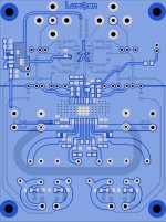
There is enough space and is good idea, I sometimes used beads on inputwires, the TH 3116 boards for example.
Wanted to add connection/provision modsel to pvcc power (tpa3128), maybe to be used for sdz just in case gvdd connection is datasheet error or not tested enough, tpa3128 evm doesn't use gvdd for sdz.
Higher temp SA5532 version is good option too. Can opa1688 or other opa's be used with same circuit (like the jfet 2134) ? Inputvoltage specs seem different to me. I do remember more standard looking, for me personally, splitters, because visually more like some dac outputstages doing the reverse and some Tubecad opamp splitter circuit I looked at that looks like those too (when making vacuum tube splitter (gyrators, cccs, powersupply noise for zero rejection tube anode ).
Hypex hinted one needs to cut open all filmcaps to see construction first for switching amps, I like that, not just ordering additional smds in case some escape when unpacking, but more violent action 🙂
I can only speak for the OPA1688 i use here. No problems in replacement of SA5532.
Another advantage is its R2R output, where the 5532 or 2134 lacks. That gives more headroom for PFFB.
Another advantage is its R2R output, where the 5532 or 2134 lacks. That gives more headroom for PFFB.
Last edited:
Also saves adding beads there then. On tpa input those beads might help a little when using pffb too. Minimum outputinductance tpa31's hints at more stable chips than tpa32's, but inside chip there is additional input parts, so still don't say anthing about functioning pffb with same circuit or close to same parts and about any benefits 🙂
Having space for beads won't hurt, those can be stuffed with 0R if not needed. I'd plan them in on the first revision.
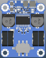
This fits instead of 78xx regulator, but is it better or will it create all kind of problems that need to be fixed that won't fit to the pcb ? How does the LM317 or transistor get rid of heat ?
Basic noise small TI 100mA 317 seems little less than half TI 78xx, bypassed r2 is said to reduce that, Panasonic electrolytic outputcap, basic capmultiplier might reduce further with small alu polymer capacitor??, there is bound to be list of "but's" to this.
Basic noise small TI 100mA 317 seems little less than half TI 78xx, bypassed r2 is said to reduce that, Panasonic electrolytic outputcap, basic capmultiplier might reduce further with small alu polymer capacitor??, there is bound to be list of "but's" to this.
Attachments
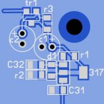
LM317 needs R2 bypass to work silent. I did tried a cap multiplier on the 3251 opamp supply. There wasn't much of an improvement as the 317 did well as postregulator of the 700kHz buck. Also the PSRR of the opamps is pretty good. As long as you keep common mode noise out, all will be fine.
Getting away the heat from the 317 is by a local polygon for pin 2 and the tap.
At 10mA and 28V PVC, that's 160mW, so a small 10x10mm will do.
Getting away the heat from the 317 is by a local polygon for pin 2 and the tap.
At 10mA and 28V PVC, that's 160mW, so a small 10x10mm will do.
Last edited:
Comparison
#1: Genuine TPA3118 on Sanwu PCB (3rd party)
#2: "Fake" TPA3118 on Sanwu PCB (3rd party)
Detailed measurements of #1 are starting from here:
http://www.diyaudio.com/forums/clas...ng-them-everything-comes-167.html#post4962346
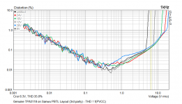
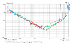
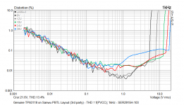
THD = f(PVCC)
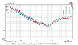
Genuine TPA3118 1kHz:

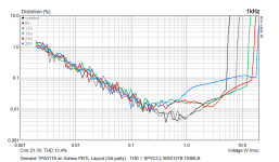
"Fake" TPA3118 1kHz:

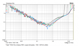
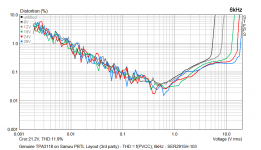
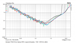
Genuine TPA3118 6kHz:

"Fake" TPA3118 6kHz:

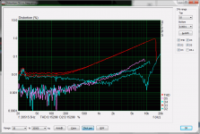
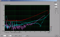
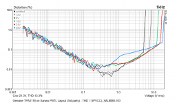
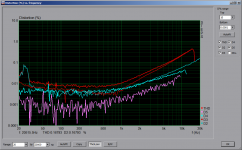
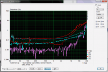
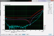
THD = f(frequency) at 1W into 4R at 12V:
Genuine TPA3118:

"Fake" TPA3118:

Nothing uncommon to see here, small differences are due to inaccuracy of the setup and part variations.
From this point of view, i'd call it the same silicon.
#1: Genuine TPA3118 on Sanwu PCB (3rd party)
#2: "Fake" TPA3118 on Sanwu PCB (3rd party)
Detailed measurements of #1 are starting from here:
http://www.diyaudio.com/forums/clas...ng-them-everything-comes-167.html#post4962346
THD = f(PVCC)
Genuine TPA3118 1kHz:
"Fake" TPA3118 1kHz:
Genuine TPA3118 6kHz:
"Fake" TPA3118 6kHz:
THD = f(frequency) at 1W into 4R at 12V:
Genuine TPA3118:
"Fake" TPA3118:
Nothing uncommon to see here, small differences are due to inaccuracy of the setup and part variations.
From this point of view, i'd call it the same silicon.
Attachments
-
 TPA3118_Sanwu_FakePCB_orig_Chip_THD_vs_PVCC_6kHz.png14.4 KB · Views: 535
 -
 TPA3118_Sanwu_FakePCB_orig_Chip_THD_vs_PVCC_1kHz.png24.1 KB · Views: 524
 -
 TPA3118_Sanwu_FakePCB_orig_Chip_1W_in_4R_12V.png20.2 KB · Views: 537
 -
 TPA3118_Sanwu_FakePCB_fake_Chip_THD_vs_PVCC_6kHz.png24.8 KB · Views: 524
 -
 TPA3118_Sanwu_FakePCB_fake_Chip_THD_vs_PVCC_1kHz.png24.2 KB · Views: 527
 -
 TPA3118_Sanwu_FakePCB_fake_Chip_1W_in_4R_12V.png21.3 KB · Views: 529
This looks the same to me, but remains chiptopsurface is polished/sanded/removed and re-lasered.(What's left of recessed/dimple dot is underneath big laserdot, in position one expects it to be, not in center of big laserdot).
A copy would not be sanded I guess, so stolen batch maybe they fear would be traceable ?
A copy would not be sanded I guess, so stolen batch maybe they fear would be traceable ?
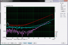
And the rest of inductor measurements. All inductors are 10uH nominal.
Tests were done at
PVCC: 19V noDiode
Load: 4R resistive
Frequency 1/6kHz
Comparison:
#1: noName stock inductors
#2: Coilcraft XAL8080-103
#3: Coilcraft MSS1278-103
#4: Coilcraft SER2915H-103
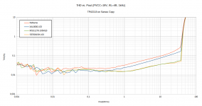
Previous measurements showed the performance limits of the actual implementation, when using the oversized SER2915H inductors. Another two inductors where tested, XAL8080 (carbonyl molded) and MSS1278 (ferrite wound). From the measurements it can be seen that the MSS1278 also perform on the implementation limits while the XAL8080 isn't much of an improvement.
Compared to datasheet (Fig.7), performance at ~1W@4R (12V) seems to better than EVM. (I know this is BTL plot but anyway)
1kHz into 4R:
noName Stock:

Coilcraft XAL8080-103:

Coilcraft SER2915H-103:

Coilcraft MSS1278-103:

6kHz into 4R:
noName Stock:

Coilcraft XAL8080-103:

Coilcraft SER2915H-103:

Coilcraft MSS1278-103:

At 19V all in one diagram:

The MSS1278 will fit, tightly.
Tests were done at
PVCC: 19V noDiode
Load: 4R resistive
Frequency 1/6kHz
Comparison:
#1: noName stock inductors
#2: Coilcraft XAL8080-103
#3: Coilcraft MSS1278-103
#4: Coilcraft SER2915H-103
Previous measurements showed the performance limits of the actual implementation, when using the oversized SER2915H inductors. Another two inductors where tested, XAL8080 (carbonyl molded) and MSS1278 (ferrite wound). From the measurements it can be seen that the MSS1278 also perform on the implementation limits while the XAL8080 isn't much of an improvement.
Compared to datasheet (Fig.7), performance at ~1W@4R (12V) seems to better than EVM. (I know this is BTL plot but anyway)
1kHz into 4R:
noName Stock:
Coilcraft XAL8080-103:
Coilcraft SER2915H-103:
Coilcraft MSS1278-103:
6kHz into 4R:
noName Stock:
Coilcraft XAL8080-103:
Coilcraft SER2915H-103:
Coilcraft MSS1278-103:
At 19V all in one diagram:
The MSS1278 will fit, tightly.
Attachments
-
 TPA3118_Sanwu_FakePCB_orig_Chip_THD_Inductor_Comparison.png54 KB · Views: 503
 -
 TPA3118_Sanwu_FakePCB_orig_Chip_THD_vs_PVCC_6kHz_XAL8080-103.png24.7 KB · Views: 500
 -
 TPA3118_Sanwu_FakePCB_orig_Chip_THD_vs_PVCC_6kHz_SER2915H.png15 KB · Views: 506
 -
 TPA3118_Sanwu_FakePCB_orig_Chip_THD_vs_PVCC_6kHz_MSS1278-103MLB.png24.9 KB · Views: 507
 -
 TPA3118_Sanwu_FakePCB_orig_Chip_THD_vs_PVCC_6kHz.png14.4 KB · Views: 502
 -
 TPA3118_Sanwu_FakePCB_orig_Chip_THD_vs_PVCC_1kHz_XAL8080-103.png24.5 KB · Views: 490
 -
 TPA3118_Sanwu_FakePCB_orig_Chip_THD_vs_PVCC_1kHz_SER2915H.png24.6 KB · Views: 503
 -
 TPA3118_Sanwu_FakePCB_orig_Chip_THD_vs_PVCC_1kHz_MSS1278-103MLB.png25.2 KB · Views: 510
 -
 TPA3118_Sanwu_FakePCB_orig_Chip_THD_vs_PVCC_1kHz.png24.1 KB · Views: 505
Last edited:
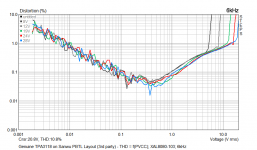
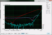
Last addition, THD vs. frequency at 1W into 4R at 24V:
noName stock:

SER2915H-103:

MSS1278-103:

noName stock:
SER2915H-103:
MSS1278-103:
Attachments
So only for treble >1kHz or >4kHz 3rd harmonic is dominant distortion for the better inductors, with stock ones for every frequency.
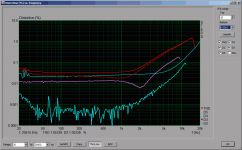
10W into 4R at 12V:
noName Stock:

SER2915H-103:

MSS1278-103:

noName Stock:
SER2915H-103:
MSS1278-103:
Attachments
Definitely same silicon.
"Fakes" could be (in order of decreasing probability):
- parts packaged by a different packaging vendor
- parts failed some test, which was then discovered to be problem with the test
- stolen parts
- parts made from stolen wafers
- parts made in the same fab/process with copied masks
"Fakes" could be (in order of decreasing probability):
- parts packaged by a different packaging vendor
- parts failed some test, which was then discovered to be problem with the test
- stolen parts
- parts made from stolen wafers
- parts made in the same fab/process with copied masks
I assumed "laserdot, but was it the "laserdot" fake one(s) you tested or another "off" print fake one(s) or a mix of all of them ?
Like those you sent me. The "laserdot fakes". (4AAD6TTG4)
The inductor-tests (SER2915H, MSS1278, XAL8080) where all done with an original TPA3118 soldered to the sanwu-like board.
The inductor-tests (SER2915H, MSS1278, XAL8080) where all done with an original TPA3118 soldered to the sanwu-like board.
- Home
- Amplifiers
- Class D
- Cheap TPA3118D2 boards, modding them and everything that comes with it