For info, the new opa2134pa looks different than the old package. You can see the new one on the first pic. It seems now easy to counterfeit the new 2134pa because the notch style is exactly same as TI tl072(which is also a jfet input opamp).


.jpg")
A large number of the fakes can be identified by just putting a square wave through them and looking at the output on a scope. Most of the fakes are made from terrible old slow part numbers like LM358. Compare the scope output with a few reference genuine parts. At this point I suggest only going to real distributors as online seems close to selling 100% fakes. Unfortunately there are many 5-star reviews left for LM358 marked as a high performance part number...

Because i don't have an oscilloscope i always buy from big online distributors like mouser, digikey etc. Those opa2134pa are from rs components.A large number of the fakes can be identified by just putting a square wave through them and looking at the output on a scope. Most of the fakes are made from terrible old slow part numbers like LM358. Compare the scope output with a few reference genuine parts. At this point I suggest only going to real distributors as online seems close to selling 100% fakes.....
LM324 has the same problem. That IC made me never use op-amps in the signal path. 😉The worst issue when you use an LM358 for audio is the enormous crossover distortion of its class-C output stage (unless you deliberately bias it in class A with an external current source or resistor).
(There are good op-amps today, but back then, the bar was very low).
Ed
I can still hear past 12k and opa2134 may just barely beat the outstanding LF353n
I used these since the 80s when I could hear past 16k. Flyback whine from a bad TV flyback was annoying. The lf353 is still one of best for stability at gains of unity to 30. I can't tell the difference between the 2 in the tone circuit of sx-3700.
I used these since the 80s when I could hear past 16k. Flyback whine from a bad TV flyback was annoying. The lf353 is still one of best for stability at gains of unity to 30. I can't tell the difference between the 2 in the tone circuit of sx-3700.
'358/'324 were specifically designed and originally marketed at automobiles. Speed is not too important in a fuel-gauge. Crossover will settle out fast enough. To-ground swing may be, and back then they thought idle current would matter. (Instead my new Toyota will have a bigger generator and battery than my 1961 Jeep.)back then, the bar was very low
FWIW- when I first tried a '324 in PA the crossover was offensive right away, and yet in another world they run '324 like they were audio chips. If your peak swing is not-large and your load impedance is high, like 2V peak in 50K, there is no crossover distortion.
There is a pull-down current source of nominally 50 uA, but it is only guaranteed to be greater than 20 uA if I recall correctly.
On the TI site, someone asked about the common mode input capacitance of the new H version vs. the older version, and in the thread, TI posted a very favorable curve. The older part's input CM capacitance varies with voltage significantly, and this causes 2nd harmonic distortion in a non-inverting amplifier used with a high and/or unbalanced source impedance at the op amp inputs. Since people often use FET amplifiers with high impedance sources, yet use low impedance feedback networks to reduce noise, this can cause excess 2nd harmonic distortion. I used this "2nd harmonic generator" as an effect with a tone stack filter circuit used in a digital delay feedback loop, in order to gunk up the overly clean digital delay and get closer to a cheap tape slapback sound - worked great.For hifi audio i don't consider TL072H as an upgrade over old & still very popular TL072A.
Here's the TI thread with the old and new CM capacitance curves. Of course, your threshold for good / no good is up to you, but the new one is cleaner though, especially for certain applications that are typical to FET input amplifiers. The datasheet alone claims over 20dB less midband distortion as well, presumably unrelated to CM capacitance and noninverting stages.
https://e2e.ti.com/support/amplifie...nce-distortion-issues-the-old-jfet-models-did
But the input voltage noise is very high compared to the old one. I think this new version is good for instrumental work. Anyway i thank you for sharing this info with us.
Best regards
Best regards
But the input voltage noise is very high compared to the old one.
That alone would have been a deal-breaker back in the day, especially in pro-sound products and studio gear, many of which used TL072's throughout.
IMHO today the best OpAmp for audio applications is OPA192. The one and only which can be used both for Power Amps and PhonoPre without any DC servos or electrolytes.
Don't you think 37nV/rtHz is too high for todays standard?That alone would have been a deal-breaker back in the day, especially in pro-sound products and studio gear, many of which used TL072's throughout.
Yes, of course, I just meant even back then it would have been unacceptable. I forgot the 'even'...
On the TI site, someone asked about the common mode input capacitance of the new H version vs. the older version, and in the thread, TI posted a very favorable curve. The older part's input CM capacitance varies with voltage significantly, and this causes 2nd harmonic distortion in a non-inverting amplifier used with a high and/or unbalanced source impedance at the op amp inputs. Since people often use FET amplifiers with high impedance sources, yet use low impedance feedback networks to reduce noise, this can cause excess 2nd harmonic distortion. I used this "2nd harmonic generator" as an effect with a tone stack filter circuit used in a digital delay feedback loop, in order to gunk up the overly clean digital delay and get closer to a cheap tape slapback sound - worked great.
Neat trick. The old Roland Space Echo had a nice bit of grunge on the tape feedback, randomized the multiecho signal nicely.
I wonder if anyone's used a varactor as a second harmonic generator?
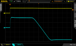
Here's an LM358 configured as an inverting amplifier with bipolar ±10V power supplies. First picture shows the response to a +500 mV input step (input hi, output low (eventually)). Second picture shows the response to a 5kHz input sinewave at approx 8V peak-to-trough. Input yellow, output blue. Executive Summary: barrrrrffff.
_
_
Attachments

With op amps I found the spec for max frequency only works for a small signal.
With large signals the max frequency is much less.
So had to use a better op amp for my oscilloscope circuit.
Better frequency and slew rate required.
With large signals the max frequency is much less.
So had to use a better op amp for my oscilloscope circuit.
Better frequency and slew rate required.
Mark Johnson - The LM358 appears to be working as expected (crossover notch of 3 Vbe drops traversed at 0.5V/us). 🙁
Ed
Ed
- Home
- Design & Build
- Parts
- Cheap JFET input op-amp