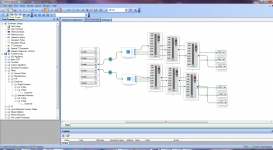
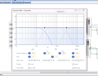
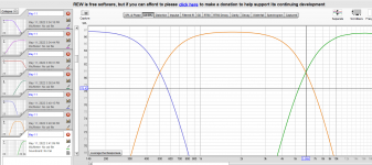
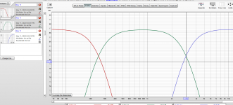
Dear friends, unfortunately, I still need your help. Managing this board is more complicated than expected. I created projects in Sigmastudio with both IIR and FIR crossovers apparently working. I export the system files on the board and here too everything is OK. Unfortunately, when I send an audio signal, the responses do not match the filters I set. So it seems that it is the card that is not working properly because in sigmastudio everything is apparently OK. I also flashed with ss_app_sh489.ldr but the situation remained unchanged. I noticed that the crossover points that come from the board are exactly twice as many as those set in sigmastudio (500 instead of 250 and 6000 instead of 3000 Hz) I attach some pictures of a very simple project showing the issue. What do you advise me to do? What can it be? I am sure you will be able to help me. Thanks in advance
Attachments
So I understand that filtering works on DSP just wrong values? You set everything in sigmastudio, export, flash and then make measurements in REW?
Try changing project sample rate to 96kHz and see if that change anything

Try changing project sample rate to 96kHz and see if that change anything
Ahahahah, you are a genius (and I am probably a fool). The solution was under my nose and I hadn't seen it! Thank you very much for the suggestion that spared me a sleepless night. at this point, however, I ask you: how to make the system work at 48 kHz?So I understand that filtering works on DSP just wrong values? You set everything in sigmastudio, export, flash and then make measurements in REW?
Try changing project sample rate to 96kHz and see if that change anything
View attachment 1053185
Attachments
Well its not so obvious.. looks like setting in Sigmastudio only change project sample rate and DSP internally still work in 96kHz cause its set like this in firmware. So to change internal sample rate.. enable ASRC (that would make my project much easier), configure SPORT etc would need to compile new firmware and flash it. I was thinking about it but not sure if I can brick GPU if firmware is 'not compatible'? There is source code available for Analog Devices eval board.. so it is possible to load that project to CrossCore, make changes, compile and flash .hex file ... will it work or brick DSP.. no idea 😀
Theoretically whole firmware is in SPI Flash so flashing again with backup should be an option(?)
safe option would be JTAG like ICE-1000 with live debug.. but that cost a bit..
I would be very happy to put my hands on configuring SHARC via firmware also 🙂
Theoretically whole firmware is in SPI Flash so flashing again with backup should be an option(?)
safe option would be JTAG like ICE-1000 with live debug.. but that cost a bit..
I would be very happy to put my hands on configuring SHARC via firmware also 🙂
This could be of some help ...Well its not so obvious.. looks like setting in Sigmastudio only change project sample rate and DSP internally still work in 96kHz cause its set like this in firmware. So to change internal sample rate.. enable ASRC (that would make my project much easier), configure SPORT etc would need to compile new firmware and flash it. I was thinking about it but not sure if I can brick GPU if firmware is 'not compatible'? There is source code available for Analog Devices eval board.. so it is possible to load that project to CrossCore, make changes, compile and flash .hex file ... will it work or brick DSP.. no idea 😀
Theoretically whole firmware is in SPI Flash so flashing again with backup should be an option(?)
safe option would be JTAG like ICE-1000 with live debug.. but that cost a bit..
I would be very happy to put my hands on configuring SHARC via firmware also 🙂
https://ez.analog.com/dsp/sigmadsp/f/q-a/540271/adau1452-sampling-frequency
If we had ADAU 1452 then yes, they moved most of config to SigmaStudio. SHARC config is in VisualDSP files ( C/C++ Language) need change source code, compile, flash (or find other firmware) no other way. Think thats cause ADAU are low cost consumer chips, and SHARC is more pro, maybe other reason like release date.
Bit different case, but thats how dsp is configured
https://ez.analog.com/dsp/sharc-processors/f/q-a/542634/audio-dac-using-adsp-21489
But Im thinking more and more about trying, boards we have are basic.. RAM, SPI Flash + some STM chip for flashing that SPI
If I get confirmation from someone who know bit more how it work, so I know I wont brick dsp easy I will do it.
I want to unleash power of SHARC 🙂
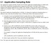
I searched for information and found these documents. Perhaps it might be enough to change some parameters in CrossCore Embedded as indicated in section 3.1 application sampling rate?If we had ADAU 1452 then yes, they moved most of config to SigmaStudio. SHARC config is in VisualDSP files ( C/C++ Language) need change source code, compile, flash (or find other firmware) no other way. Think thats cause ADAU are low cost consumer chips, and SHARC is more pro, maybe other reason like release date.
Bit different case, but thats how dsp is configured
https://ez.analog.com/dsp/sharc-processors/f/q-a/542634/audio-dac-using-adsp-21489
But Im thinking more and more about trying, boards we have are basic.. RAM, SPI Flash + some STM chip for flashing that SPI
If I get confirmation from someone who know bit more how it work, so I know I wont brick dsp easy I will do it.
I want to unleash power of SHARC 🙂
The sample rate must absolutely be changed, I do not understand why they brought it to 96K when 48k is the default. At 96k it takes many more taps to create a valid FIR filter, and these deplete system resources.
Is it possible that no one has reported the sample rate of the card to the original 48k and that they cannot provide us with information on how to do it?
https://ez.analog.com/dsp/software-...gmastudioforsharc-2-2-0-adsp-213xx-adsp-214xx
Attachments
To be honest Im happy with 96khz, I dont think I will need so much compute power for my filters, also signal should be upsampled before filtering and processing on 48khz seems low imo. Nice finding, if that works without compiling and flashing .hex files would be great.
Nice finding, I would give it a try, just change settings in CCES and compile/flash sigma files only.
Let me know if that works for you
Nice finding, I would give it a try, just change settings in CCES and compile/flash sigma files only.
Let me know if that works for you
Unfortunately I'm just an enthusiast and I don't have the skills to execute the instructions correctly. I would need a step-to-step guide to proceed. For me the computing power is important because currently I have a 4-way active system with FIR filters with a very high number of taps (I have a very powerful computer), but I also wanted to try the DSP solution from Analog Devices to avoid always turning on the PC. My idea was to use two 21489 cards, one for each loudspeaker, but even so with the sampling rate at 96KHz I cannot make good linear FIR filters at low frequenciesTo be honest Im happy with 96khz, I dont think I will need so much compute power for my filters, also signal should be upsampled before filtering and processing on 48khz seems low imo. Nice finding, if that works without compiling and flashing .hex files would be great.
Nice finding, I would give it a try, just change settings in CCES and compile/flash sigma files only.
Let me know if that works for you
Well I am no professional also. Had xover on PC also via VST plugins or EqualizerAPO, and i see DSP much more convenient, flexible and stable for me.
If I understand manual correctly and there is no need for flashing .hex files.. (but I still doubt this)
Then you just need to open CCES, open project and look for 21489 demo prj.. there should be folder somewhere is CCES
For me its here:

And then as in pdf .. change sample rate settings:

Theoretically SigmaStudio use CCES to compile its projects, so maybe changing this will work, but never tried.
If you need to compile sources in CCES and flash .hex file to make changes work then it can be more complicated - dont think this demo app have same RAM for example ( or is it autodetected by dps? ) so there can be compatibility issues. I would try flash this demo .hex but afraid to brick DSP at the moment, while im not sure how it works 100%.
Probably very easy questions for someone who had experience making custom dsp board/firmware.
If I understand manual correctly and there is no need for flashing .hex files.. (but I still doubt this)
Then you just need to open CCES, open project and look for 21489 demo prj.. there should be folder somewhere is CCES
For me its here:
And then as in pdf .. change sample rate settings:
Theoretically SigmaStudio use CCES to compile its projects, so maybe changing this will work, but never tried.
If you need to compile sources in CCES and flash .hex file to make changes work then it can be more complicated - dont think this demo app have same RAM for example ( or is it autodetected by dps? ) so there can be compatibility issues. I would try flash this demo .hex but afraid to brick DSP at the moment, while im not sure how it works 100%.
Probably very easy questions for someone who had experience making custom dsp board/firmware.
Was wondering if you got any luck with changing sample rate
I was even thinking about buying JTAG debugger - there I found cheaper chineese clone which is still $350 but significantly less than original like $1500
Would be nice to have multiple firmware - with/without ASRC, TDM/I2S out, DIRAC, audioweaver and so on.
Board itself cost like $90 think its great value and great alternative for camillaDSP for example.
Are there more people interested in this topic?
No, I haven't solved it yet. I confess that the board is unusable for me at this sample rate, so if I don't find a way to change it I will abandon any project with this processor. We probably have to open a new thread with the specific request to hope someone will help usWas wondering if you got any luck with changing sample rate
I was even thinking about buying JTAG debugger - there I found cheaper chineese clone which is still $350 but significantly less than original like $1500
Would be nice to have multiple firmware - with/without ASRC, TDM/I2S out, DIRAC, audioweaver and so on.
Board itself cost like $90 think its great value and great alternative for camillaDSP for example.
Are there more people interested in this topic?
It seems easy to change sample rate for someone who have JTAG and some experience and board is very basic - just SPI flash and bare pins for I2S. Im also wondering wouldnt it be possible to play with firmware - change what you need, compile and write, if you dump current SPI Flash and save it as backup? If there is problem just Flash backup with programmer?
Yes, but to spend $350 for the JTAG programmer for a $90 board seems a bit odd. That overall price puts a lot of other products in the mix.
Any example? Where it comes to compute power and flexibility (with JTAG) ? And I found another one on ebay for $100 but its some budget variant -5Mhz, and that one for $350 is 45Mhz.. if it make any difference in debugging(?)
So, I'm to the point where I can incorporate the schematics exported from sigmastudio into the demo schematics for the ADSP-21489. My issue comes in that I do not have the Custom Board Configuration file to setup the memory use correctly (fully optimized). I also had to change settings for the compilation in CCES in order for it to properly set the memory internal to the chip (L2) for the mem_5 settings when following the changes in a PDF on how to make a bootable application for these systems. I found a couple ICE-1000s on ebay in the $115-130 price range I might snap up.Well I am no professional also. Had xover on PC also via VST plugins or EqualizerAPO, and i see DSP much more convenient, flexible and stable for me.
If I understand manual correctly and there is no need for flashing .hex files.. (but I still doubt this)
Then you just need to open CCES, open project and look for 21489 demo prj.. there should be folder somewhere is CCES
For me its here:
View attachment 1053812
And then as in pdf .. change sample rate settings:
View attachment 1053813
Theoretically SigmaStudio use CCES to compile its projects, so maybe changing this will work, but never tried.
If you need to compile sources in CCES and flash .hex file to make changes work then it can be more complicated - dont think this demo app have same RAM for example ( or is it autodetected by dps? ) so there can be compatibility issues. I would try flash this demo .hex but afraid to brick DSP at the moment, while im not sure how it works 100%.
Probably very easy questions for someone who had experience making custom dsp board/firmware.
But it wasn't until I changed the settings according to this post that I was able to succeed in compiling.
https://ez.analog.com/dsp/software-and-development-tools/cces/f/q-a/534784/li1040 (post answering the question)
https://ez.analog.com/cfs-file/__ke...gmaStudio_5F00_No_5F00_Download_5F00_Mode.pdf
I also set compiler optimization to on while going through settings.
And I agree with you on flashing it. Until I have a JTAG to debug and to verify there is no hang, no memory errors, etc., I would not flash something I cannot reverse, yet.
I currently have 4 of these (one per loudspeaker with three drivers in it). I am reading through this here as GiAnt found me at ToidDIY's forum.
So, the ICE-1000, which is basically the ICE-100b, is the 5MHz variant and you can buy those for around $200 on mouser/digi/etc. The 40MHz version is ICE-2000, is over $1000, and is a different beast. The cheap ones I saw on ebay are of the ICE-1000 type. So it depends. Now, this JTAG ICE (in-circuit emulator is what ICE stands for) would also be usable if you wanted to, in the future, buy the eval boards directly from ADI or on the other parts websites, with it being about $450 (when you can find them in stock) for the new ADSP-21593, which has the power of 4 x ADSP-21489. And the carrying board is able to work with other main boards, so swapping in the future drops down to $100-200 instead of replacing everything (if wanting to do upgrade-able down the line).Any example? Where it comes to compute power and flexibility (with JTAG) ? And I found another one on ebay for $100 but its some budget variant -5Mhz, and that one for $350 is 45Mhz.. if it make any difference in debugging(?)
But, yes, I will be buying an ICE-100 cheap one sometime soon. You can either wait or not. I gave links to alternatives for those not wanting to wait or do so complicated a setup.
"
Also, for those not willing to learn some programming, etc., these are better fits. One of them is for having multiple in a single speaker if doing a three way (issues of two different master oscillating crystals, will never truly sync, but you can get close with doing the delays for the drivers), whereas the other is for 8 input, 8 output, spdif in and out, etc.
https://www.aliexpress.com/item/325...216558245227396043ef032!12000022454946709!sea
https://www.aliexpress.com/item/325...216558245227396043ef032!12000024198353420!sea
Those can be fully programmed with sigmastudio without CCES. The ADAU1467 gets close to the processing power of the ADSP-21489, but it simplifies what you need greatly. Cost is about the same (if needing 2 of the first one for up to a 4-way or the second one which has all the inputs similar to the board we are working on).
Verify first with the vendor, for the first link, whether the boards have the 1463 or the 1467. Also verify what ADC and DAC is being sent with the board. For the second link, it is plug and play using 3.5mm aux. two channel plugs.
But those would likely be simpler for many to work with, while providing what they need. In fact, two of the first link would, in theory, have more taps available than the adsp-21489. Once again, synchronization issues may arise, but should be minimal. There are numerous ways to handle two in a single system.
I am still working on an error in CCES when building the application project. I’ll report when I have more info."
I solved the compilation error I was having with CCES when I incorporated the system file into my program in CCES. See response above on the settings for the li1040 error.
https://toidsdiyaudio.com/forums/di...ing-different-hardware-etc/page/7/#post-25233basic software for Ali adsp21489 development board
Hello,
I bought this board but I could not yet find the basic software for it. It is promised on this page with the reference below. I mailed the Chinese Ali seller but they had only the hardware reference manual no basic software. do you have any pointers?
Kind regards Jaap Beekman
Dsp Elektronische Crossover/Adi Sharc Development Board / ADSP 21489 Development Board|Air Conditioner Parts| - AliExpress
Look for the wetransfer zip file. That is the one I got with mine. I would post it here, but it said the zip file was too large for the forum. I'm not going to break it down and describe how to use it fully here.
Basically first start the USB midi file. Then start the version of the program with either english or chinese. Then download your settings to the system and enjoy. You will not be able to communicate with the board through the micro-usb unless you open the USB midi program first. The connect in the main program is in the upper left corner.
Sorry Google Translate.
I write in Russian - Пишу на русском.
В пакете представленном по ссылке на ГуглДиск есть утилита для записи готового проекта SigmaStudio (SS) в память DSP.
Вы невнимательно смотрели видео! Нужно четвертое видео
Это не мои видео. Я не автор видео! 🙂
Я исследовал какой длины можно сделать FIR фильтр при текущих настройках на 96 kHz. Это 4000 тапов при 96 kHz. Больше получить нельзя!
Как переключить частоту на 48 kHz я не знаю! 🙂
Для чего на плате припаяна микросхема RAM на 8MB я не знаю. Подключить её я не смог. 🙂))
Расписываю тайминг ролика для записи проекта SigmaStudio (SS) в ROM DSP (как понимаю это память STM):
6:05 - перевод платы на управление из SS через USB-i переходник. Самый главный - это программа-прошивальщик CoreBoard Upgrade.exe
18:18 - начинается рассказ о том, что все настройки только в RAM и пропадут при выключении питания.
18:50 - нужно экспортировать свой проект из SS.
19:12 - экспорт проекта (Export System Files) из SS в нужный для прошивальщика CoreBoard Upgrade.exe
19:22 - экспортируемые файлы SS записываем в папку прошивальщика \Sigma_Files\
Существующие в папке файлы нужно удалить, чтобы папка была чистой перед записью вашего проекта!!!
20:13 - после экспорта файлов, подключаем плату процессора напрямую к USB!
USBi отключаем!!!
20:39 - запускаем CoreBoard Upgrade.exe и нажимаем на кнопку Sigma_Files
21:38 - запись пошла.
21:54 - всё, запись прошла успешно в ROM DSP и теперь выключение питания ничего не сбросит.
Если вам не нужны FIR фильтры, то лучше использовать китайскую оболочку, которая идёт с платой.
В SS ещё нужно разобраться в нумерацией выходов ADC, а она случайная. 🙂))
Потом, если нет программы SS записанной в ROM, то возможны неожиданные щелчки на полную громкость - это пугает. 🙂
I write in Russian - Пишу на русском.
В пакете представленном по ссылке на ГуглДиск есть утилита для записи готового проекта SigmaStudio (SS) в память DSP.
Вы невнимательно смотрели видео! Нужно четвертое видео
Я исследовал какой длины можно сделать FIR фильтр при текущих настройках на 96 kHz. Это 4000 тапов при 96 kHz. Больше получить нельзя!
Как переключить частоту на 48 kHz я не знаю! 🙂
Для чего на плате припаяна микросхема RAM на 8MB я не знаю. Подключить её я не смог. 🙂))
Расписываю тайминг ролика для записи проекта SigmaStudio (SS) в ROM DSP (как понимаю это память STM):
6:05 - перевод платы на управление из SS через USB-i переходник. Самый главный - это программа-прошивальщик CoreBoard Upgrade.exe
18:18 - начинается рассказ о том, что все настройки только в RAM и пропадут при выключении питания.
18:50 - нужно экспортировать свой проект из SS.
19:12 - экспорт проекта (Export System Files) из SS в нужный для прошивальщика CoreBoard Upgrade.exe
19:22 - экспортируемые файлы SS записываем в папку прошивальщика \Sigma_Files\
Существующие в папке файлы нужно удалить, чтобы папка была чистой перед записью вашего проекта!!!
20:13 - после экспорта файлов, подключаем плату процессора напрямую к USB!
USBi отключаем!!!
20:39 - запускаем CoreBoard Upgrade.exe и нажимаем на кнопку Sigma_Files
21:38 - запись пошла.
21:54 - всё, запись прошла успешно в ROM DSP и теперь выключение питания ничего не сбросит.
Если вам не нужны FIR фильтры, то лучше использовать китайскую оболочку, которая идёт с платой.
В SS ещё нужно разобраться в нумерацией выходов ADC, а она случайная. 🙂))
Потом, если нет программы SS записанной в ROM, то возможны неожиданные щелчки на полную громкость - это пугает. 🙂

English please: saying you are doing Russian still breaks the English rule.I am writing in Russian.
In the package of the reference to Googldisk there is a utility for recording the finished project Sigmastudio (SS) in memory of DSP.
You watched the video inattentively! We need the fourth video
This is not my video. I am not the author of the video! 🙂
I investigated how long you can make a FIR filter with current 96 KHZ settings. This is 4000 slippers at 96 KHZ. You can’t get anymore!
How to switch the frequency to 48 KHZ I do not know! 🙂
Why I do not know on the board the RAM microcircuit RAM on 8MB. I could not connect it. 🙂))
I paint the timing of the video for recording the Sigmastudio (SS) project in ROM DSP (as I understand this is STM memory):
6:05 - Transfer of control from SS via USB -I adapter. The most important thing is the Coreboard Upgrade.exe
18:18 - The story begins that all settings are only in RAM and disappear when the power is turned off.
18:50 - You need to export your project from SS.
19:12 - Export System Files from SS to the Coreboard Upgrad.exe desired for the firmware
19:22 - We write the exported SS files in the firmware folder \ sigma_files \
The files existing in the folder must be deleted so that the folder is clean before the recording of your project !!!
20:13 - After the export of files, we connect the processor board directly to the USB!
We turn off USBI !!!
20:39 - Launch Coreboard Upgrade.exe and click on the Sigma_Files button
21:38 - The record went.
21:54 - That's it, the recording was successful in ROM DSP and now the power outlet will not drop anything.
If you do not need FIR filters, it is better to use the Chinese shell that goes with a board.
SS also needs to understand the numbering of ADC outputs, and it is random. 🙂))
Then, if there is no SS program recorded in ROM, then unexpected clicks are possible at full volume - it scares. 🙂
dave

diyAudio moderation team
- Home
- Source & Line
- Digital Line Level
- Cheap ADSP21489 + 4in / 6out PCM1798 board