Hi ! i need to get a single voltage for a preamp prototype with low consumption and i am thinking to batteries for a noiseless power source (Actually i have not decided yet the actual rechargeable batteries type)
If i am using SLA batteries i would need at least 3 of them in series to get around 40V that could be enough for the task ... better 4 of them My question is ... can i charge them in parallel using a 12V single powerful charger ? is it dangerous ?
the idea is to keep the charger always running and switch it off during listening Thanks a lot indeed.
Last edited:
As any voltage sources, can't be paralleled per se. It is usually advisable to use one diode in series with one of them to avoid inter-bateries charging/discharging. But usually it is better to charge in series or one per time.
In any case, batteries aren't noiseless. Perhaps less noisier than other power sources.
In any case, batteries aren't noiseless. Perhaps less noisier than other power sources.
Last edited:
As any voltage sources, can't be paralleled per se.
Hi ! thanks a lot for the very kind and valuable advice. I am very uneducated in the matter clearly
It is usually advisable to use one diode in series with one of them to avoid inter-bateries charging/discharging. But usually it is better to charge in series or one per time.
If i understand well in series no problem ? this is very important for me. But i guess i cannot use an off-the-shelf charger ... i should made a special one ? i could need 3 o 4 in series ... to get around 40-50V Is that feasible ? any advice of a good design for the task ?
i would like to get a very low noise 40-50V power supply. And a series of batteries immediately came to my mind ... 🙄 but if you have any alternative that would be much welcome and appreciated. Even if batteries intrigue me a lot ...In any case, batteries aren't noiseless. Perhaps less noisier than other power sources
 Thanks again a lot. Kind regards, gino 😀
Yes, my dear Tanito. I was born in Argentina, grandson of Italians.
There are two kinds of power sources: voltage and current sources. Voltage sources are batteries, and many other, with low (Ideally nul) output resistance. You can drain the current you want to infinite ampers.
Current sources are, for example, solar cells. They have infinite voltage at infinite resistance, so you can get from the the voltage you want.
Obviously, this short comment has its limitations, and in real world things are not so good, voltage sources has limits and also current.
Current sources may be paralleled but not wired in series. Voltage sources must not be paralleled and is OK put them in series. This is because the lower the voltage source will be the least demand for current, and vice-versa, then a ballast resistor or the like is mandatory in order to get from them, the sale performance, at the expense of increasing output impedance and making a worse voltage source. This is also valid for charger, if you have a battery with, say, 1V and other with 0.99V, then the 0.99V will demand the current from the charger until it reaches 1V, so different Ah will be put in both.
Hi ! great to know about your italian origins ... i envy your spaces ... Argentina is big like a continent ... we are too crowded here in Milan and not very educated However ... i am feeling like i have open a can full of worms ... as much as i liked the idea now the task looks too challenging to me I do not even know where to look for a suitable charger ... they are designed and built for charging just a single battery at a time ... instead i need to provide 40-50V depending if i will use 3 or 4 in series ... and i do not know about current requirements I will cancel the idea and revert to a more practical power supply Thanks a lot again Kind regards, gino
Last edited:
Hey, hey, wait a moment! Your idea is not really bad.
You give me hope ! thanks ! 😱
What is current demand you need from them?
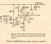
very very little ... i do not know precisely ... max 100-200 mA no more supply Voltage should be around 40-50V The original schematic i am attaching is the original ... but i am changing parameters and keep the overall concept lowering the V supply I will be using different bjts and resistors value It is a line stage ... a medium to long term project
but if you say that using a more traditional power supply will make no difference at all i will revert immediately to that solution i will look for a low noise 50V power supply ... not the most common PS but doable i guess the lower the supply noise the better of course
Attachments
Last edited:
70V for a buffer seems to be very ridiculous. You can do the same with those transistors or a opamp and only 9-12V.
70V for a buffer seems to be very ridiculous. You can do the same with those transistors or a opamp and only 9-12V
and with the same performance in terms of THD ? This simple topology can have -120dB of K1 distortion and lower K2 ... yes ... i guess a buffer would be enough for just a line stage To be completely honest another dream of mine is the diamond buffer ... following a nice attenuator
Last edited:
Not sure, but this amp gains 7 times, aprox. This is easily doable with a couple of resistors and caps, and a single opamp. Thanks for a lot of NFB, the THD will be low enough.
To charge batteries in series, their capacities must be fairly closely matched or the weakest will overcharge and degrade even more. This is a big headache on 24V vehicles
Hi thanks a lot for the helpful advice. Naturally they will be same model/part number ... but i do not know if this could be enough to avoid issues ... i do not know how much closely matched they will be. Maybe the good brand ones they will be identical enough ?
I'd say that for small VRLA batteries (up to 7AH) you could charge them in parallel providing you add small series balancing resistors of a couple of ohms. Charge them from a current limited constant voltage source of at least 14.4 volts and consider them fully charged when the current to each drops to a few tens of milliamps. Each battery should also incorporate a series fuse of just an amp or so for safety in case of shorts anywhere.
Hi thanks a lot for the kind and very useful advice. Things are becoming complicated ... There is a guy over here who was telling me that they used to work with 110V rechargeable batteries made of 91 element of 1,2V in series ... i would much prefer the recharge in series ... very much indeed. My idea was to keep the batteries on charge when not used and just switch off the charger when in use. Very easy doable ... and convenient
Hi Gino I would forget using batteries, rather study this data sheet http://www.ti.com/lit/ds/symlink/tl783.pdf You will need to create a resistive divider made from a 82 ohm and a 4700 ohm resistor see figure 20, which will provide 72V DC so extremely close to what you need with easily available resistor values- if you need 70v exactly study to find the relationship of the divider - to discover the 86 ohm instead will give 69 V To make a 86 ohm resistor use the formula R1 x R2 / R1+ R2 to find the values
and make sure you use suitably rated capacitors - particularly voltage rating that the voltage rating is at least a third again in capability so 100v rating capacitors
To create a supply with the 70V DC necessary voltage, suggest you use a transformer with 55V AC-0V secondary winding then use a conventional full wave bridge rectifier and capacitor. . If adopting that circuit exactly you will need to source the exact transistors.
You could though use much lower voltage like 20v by adjusting the resistance values downward accordingly, ie there is nothing too precious about 70v - rather you may find at a guess Radford being valve manufacturers were just using 70v derived from a higher voltage elsewhere in the chassis, or had a transformer wound on site that was a easy winding ratio relative to other transformers they were building.
Last edited:
You can’t charge series connected 12 volt batteries with a 12 volt charger unless you disconnect the series connection or you have charge each 12 volt block individually
High-voltage battery systems are a real headache - I would leave that to EV manufacturers and the like to figure out.
There are various ways of getting your +70 V:
Rummage through your stash of small transformers and see what you've got. I found a PCB mount 3 VA, 2x 24 V secondary transformer at RS Components - almost perfect. That'll give you about 65 V= - eh, good enough for Australia, as Dave Jones would say.
Don't have a 2x 24 V but maybe 2x 12 V or 1x 24 V? Time for a voltage doubler. I'm not a huge fan of voltage doubler or multiplier circuits as they are hard on capacitors and as such best used for applications with low current draw where you can resort to the more resilient film or ceramic kind. Still, you're only asking for <15 mA, not a great deal more than a mic phantom power supply (quite commonly derived in such a way).
Once you have a suitable DC voltage, you could then set out to clean it up with a capacitance multiplier. A single MOSFET cap multiplier (like Juma's) is easy to apply and might well be a near perfect fit here. Who cares about 4 V of dropout at voltages like these.
Alternatively, instead of a MOSFET you might also use a TL783 to do a similar job:
https://www.edn.com/design/power-management/4442151/LM317-smooths-but-doesn-t-regulate
Of course, you can also use it like as an ordinary regulator, complete with the ADJ pin capacitor not suggested in datasheet. (Best include 1N400x or similar diode from ADJ to OUT to allow discharging on power-down without damage. If substantial capacitance is present after the reg, another diode from OUT to IN is also advised.)
With the additional RC filtering, this may be all you need. I would change the amplifier circuit's input biasing to (R/RC - R) or (R/C - R/R) for better PSRR though. Taking the circuit as shown and splitting the 100k into 10k/10µ + 91k, I am getting about 90 dB of PSRR at 100 Hz, an improvement of ~27 dB.
Last edited:
PS:
Taking the circuit as shown and splitting the 680k into 120k/1µ + 560k, I am getting about 95 dB of effective input PSRR at 100 Hz with a 2k2 source impedance (and about the same at 12k5), an improvement of ~18 dB. The difference is even more pronounced at lower gain. Without the 220R/220µ rail filtering, the circuit itself contributes up to 66 dB once modified.
Oops, that was the input amplifier, not the output one. It should read:Taking the circuit as shown and splitting the 100k into 10k/10µ + 91k, I am getting about 90 dB of PSRR at 100 Hz, an improvement of ~27 dB.
Taking the circuit as shown and splitting the 680k into 120k/1µ + 560k, I am getting about 95 dB of effective input PSRR at 100 Hz with a 2k2 source impedance (and about the same at 12k5), an improvement of ~18 dB. The difference is even more pronounced at lower gain. Without the 220R/220µ rail filtering, the circuit itself contributes up to 66 dB once modified.
Last edited:
....i do not know precisely ... max 100-200 mA no more ....
The stage you show takes 6mA. Not hundreds.
Batteries are all LOW voltage. It is usually difficult to run high voltage gear on batteries.
You can make a wall-power supply as quiet as you need. At these low currents, a 4-stage R-C filter will get line ripple well below self-hiss.
Hi Gino I would forget using batteries, rather study this data sheet http://www.ti.com/lit/ds/symlink/tl783.pdf You will need to create a resistive divider made from a 82 ohm and a 4700 ohm resistor see figure 20, which will provide 72V DC so extremely close to what you need with easily available resistor values- if you need 70v exactly study to find the relationship of the divider - to discover the 86 ohm instead will give 69 V To make a 86 ohm resistor use the formula R1 x R2 / R1+ R2 to find the values
Hi ! thank you very much ! i know the part ...i really think i will end using it and maybe adding some passive filter as below suggested to remove the last drop of noise This part is very convenient indeed. And i do not believe that varying the Vsupply of some volts will make that big difference ... there will be a range acceptable like +/-10% ? more than enough to compensate for available resistor values ... I am sold on this part. But first i have to sim the circuit ... but i feel that this part + passive filter is the end of the game. Thank you !!! 😀
and make sure you use suitably rated capacitors - particularly voltage rating that the voltage rating is at least a third again in capability so 100v rating capacitors To create a supply with the 70V DC necessary voltage,
i surely will keep that in mind ... and also i will look for high grade capacitors The current needed is really really low ... so not many uF are really needed
suggest you use a transformer with 55V AC-0V secondary winding then use a conventional full wave bridge rectifier and capacitor

If adopting that circuit exactly you will need to source the exact transistors. You could though use much lower voltage like 20v by adjusting the resistance values downward accordingly, ie there is nothing too precious about 70v - rather you may find at a guess Radford being valve manufacturers were just using 70v derived from a higher voltage elsewhere in the chassis, or had a transformer wound on site that was a easy winding ratio relative to other transformers they were building
i understand perfectly your point. But the availability of the part above mentioned is too good to be true ... very great part indeed. But i need to play first a littl with simulator SW to see how the V supply influences the distortion ... This very simple circuit is perfect for very simple simulations. Moreover i have gathered so many positive reviews of the sound of the original unit that motivate me a lot I am sure that with some parts selection and simulation a clone could be even better than the already good original This preamp is my first impact with audio projects ... before now i have only recapped something and often made disasters. In particular in the attempt to reduce the gain of an integrated amp to use it as a power buffer for a headphone amp i got some oscillations and burnt the output bjts ... The reason behind that is that often i am forced to headphone listening because i listened late in the night. So an old idea as been to select a very nice sounding heaphone amp solution and adopt it as a line preamp to get similar sound from speakers. Problem is that the voltage output is too high for a standard power amp. Often a V gain of 4-5 in the power amp would be enough
To end my ramblings ... if the simulation will show that there are real benefits with higher V supply i surely will use the TI part you mentioned. Thanks a lot again. Kind regards, gino
Last edited:
- Home
- Amplifiers
- Power Supplies
- Charging batteries in parallel