The resistors are constant current source sink, that's why 30mA draw with 500R, when changed to 750R - 23mA and stable 15V at 3mA on input transistors. Before 750 wasn't enough for 15V with such load. Will try 1K later on.
Last edited:
Base resistors in the drivers didn't help to raise the bias current of OP.
What about base resistors of Vbe multipliers?
What about base resistors of Vbe multipliers?
Tried to change base resistors on drivers to 100R and on Vbe multiplier to 260R - very minimal change in OP bias current.
Also I changed 1N4148 diodes to red LEDs as per SSA BIBGT HP LC schematic he used in his amplifier.
Does someone know why OP bias current not working?
Also I changed 1N4148 diodes to red LEDs as per SSA BIBGT HP LC schematic he used in his amplifier.
Does someone know why OP bias current not working?
Thanks Stee for the hint.
Should it be complementary devices from both sides? Do they need matching?
Should it be complementary devices from both sides? Do they need matching?
Hi, guys.
I don't really get this amplifier. Is it intended to be driven balanced?
If so, how can it work? As I see it, the plus and minus inputs makes the whole thing tilt if driven balanced. It can only operate if both sides have the same signal.
Maybe I'm a bit summer-disoriented. Actually it's very plausible.
Hi Stee.
Do you mean Wilson driver pair should be arranged something like this? Those transistors are in place of bias current set resistors, supposedly they set the bias current for the drivers.
Do they need to be mounted on the heatsink like drivers (on the same heatsink as drivers)?
Do you mean Wilson driver pair should be arranged something like this? Those transistors are in place of bias current set resistors, supposedly they set the bias current for the drivers.
Do they need to be mounted on the heatsink like drivers (on the same heatsink as drivers)?
Hi - they do not need matching because driver have gain one on each rail
Attachments
Is it intended to be driven balanced?
If so, how can it work? As I see it, the plus and minus inputs makes the whole thing tilt if driven balanced. It can only operate if both sides have the same signal.
Yes, it is.
I haven't tried it to play yet. LC thought it should work.
It should operate if both sides have a differential signal I think.
OK, an example , Andriy.
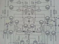
Take the 970bl transistors at the input. If the plus input takes 1V and the minus input takes -1V then the the current through the two 970BL will be appr. 2V/(2*10 ohm) = 0.1A.
This isn't realistic, so it wont work balanced. But if you remove the minus input the amp will work properly. I think.
What was your intention with this design? It's a bit unusual.
The intention is obvious - balanced amp.
Perhaps it's wiser to try to remove all transistors from the minus input, not only a970, and make it SE input.
Why do you think it's not realistic? How do you think it should be acomplished balanced correctly?
Perhaps it's wiser to try to remove all transistors from the minus input, not only a970, and make it SE input.
Why do you think it's not realistic? How do you think it should be acomplished balanced correctly?
Hi Stee.
Tried your solution but without change, even little more unstable. I tried it in a version with 5 diodes string without Vbe multipliers.
The most stable condition the amp has when input aren't shorted to ground and transistors are little warm.
Tried your solution but without change, even little more unstable. I tried it in a version with 5 diodes string without Vbe multipliers.
The most stable condition the amp has when input aren't shorted to ground and transistors are little warm.
Now I get it. The reason that your amp actually seems to work is that if the minus input is unconnected it will "float along" with the plus input and nothing will happen. But when you one day will try to drive it balanced it will fail.
I can't really see how to make your amp balanced without totally redesign it.
When I asked for your intention, I referred to both the input section - which normally is an LTP - and the usage of the CFP configurated drivers.
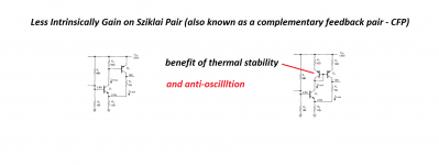
Personally, I'm a bit suspicious to NFB within global NFB loop. The CFP has a little feedback path in itself. The reduction of THD is insignificant compared to the output section. And it will perhaps make the amp slightly harder to make stable.
But the input section looks a bit like a singleton input. And that's nice.
I can't really see how to make your amp balanced without totally redesign it.
When I asked for your intention, I referred to both the input section - which normally is an LTP - and the usage of the CFP configurated drivers.
Personally, I'm a bit suspicious to NFB within global NFB loop. The CFP has a little feedback path in itself. The reduction of THD is insignificant compared to the output section. And it will perhaps make the amp slightly harder to make stable.
But the input section looks a bit like a singleton input. And that's nice.
As I know the minus input section is connected in a way of Lender's circuit.
You are saying this schematic will work only as SE without minus input components.
Do you know in what way the schematic should be redesigned to work correctly?
Is there somewhere other working discrete balanced amplifier schematic to compare? I couldn't find it.
You are saying this schematic will work only as SE without minus input components.
Do you know in what way the schematic should be redesigned to work correctly?
Is there somewhere other working discrete balanced amplifier schematic to compare? I couldn't find it.
Last edited:
Haven't you simulated the circuit?
But I don't think it's a big deal. Single ended operation will mostly do just fine, except if the cables are long.
But I don't think it's a big deal. Single ended operation will mostly do just fine, except if the cables are long.
No I have no the working model. A few pages back Cortez tried to simulate it without success, the files are there, perhaps doing something wrong.
I suspect removing minus input components won't affect its stability.
Do you know how to make Vbe multiplier to work? There is only 3mA (should be at least for VAS to work) bias current on the input transistors in stable condition, however optimum is 4.5mA.
I suspect removing minus input components won't affect its stability.
Do you know how to make Vbe multiplier to work? There is only 3mA (should be at least for VAS to work) bias current on the input transistors in stable condition, however optimum is 4.5mA.
Why not use a "normal" VBE multiplier? It should give the proper temp compensation.
But I really think you should use a simulator. I would never design an amp without simulations. Actually I did so some twenty years ago and the outcome wasn't too good.
The pitfalls are numerous when trying to calculate things the old way.
The simulator has made me lazy, I admit that. Nowadays I simulate even the simplest of all circuits and it's surprisingly common that even they behave differently than what you might think.
But I'm that kind of person that hate details. 🙂
Which is normal vbe multiplier?
Could you please simulate it? The latest file is at post 55.
Could you please simulate it? The latest file is at post 55.
Last edited:
Symmetric Vbe multiplier in this amplifier is no problem - I used this kind of configuration in some of my amplifiers.
The problem, related to this project is not related to technical matters - it's rather related to strategic approach 😉 - trying to build something with not enough understanding of the circuit operation and no support from original circuit designer - requires lots of time and effort.
If the goal is the process, not the result - that's fine. Otherwise, that's a really thorny path to successful build 🙄
- Status
- Not open for further replies.
- Home
- Amplifiers
- Solid State
- CFP Amplifier - Help Please!