I never said they are genuine but they work. Also, some humble workhorse actives aren't going to be faked. BC547/557, BC550/560, J110, J310, 2SC1845 etc. I measure my caps with LCR meter and they are within spec. Always on the low end so 2200uF is really 2000uF.
What's the point of wasting time and efforts on building amps with inferiorI never said they are genuine but they work. Also, some humble workhorse actives aren't going to be faked. BC547/557, BC550/560, J110, J310, 2SC1845 etc. I measure my caps with LCR meter and they are within spec. Always on the low end so 2200uF is really 2000uF.
parts? Price wise, it's cheaper to buy them from Best Buy.
It's about building amps that are better than that, and this can't be done
with fake parts from Aliexpress...
What's the point of wasting time and efforts on building amps with inferior
parts? Price wise, it's cheaper to buy them from Best Buy.
It's about building amps that are better than that, and this can't be done
with fake parts from Aliexpress...
Not going to argue about this. Just letting people know there are options. I have about a dozen amps that would tell you otherwise about how good Chinese sourced parts can sound. Many components actually originate from China (according to my genuine parts compliance statement from Digikey) so doesn't surprise me.
You can look at my amps (more than a dozen and counting) and even listen to them - most made with AliExpress sourced parts. Some parts I got from Digikey, but I found no difference in sound quality. And I am quite certain they sound much much better than any amp from BestBuy 🙂
http://www.diyaudio.com/forums/solid-state/295286-virtual-audition-very-simple-quasi-mosfet-amp.html
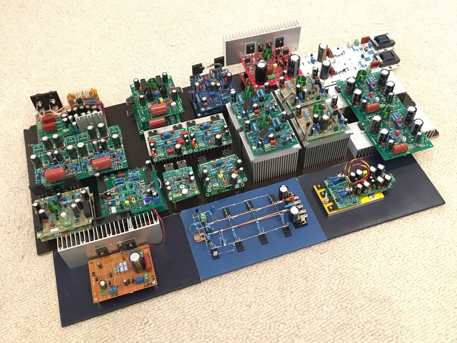
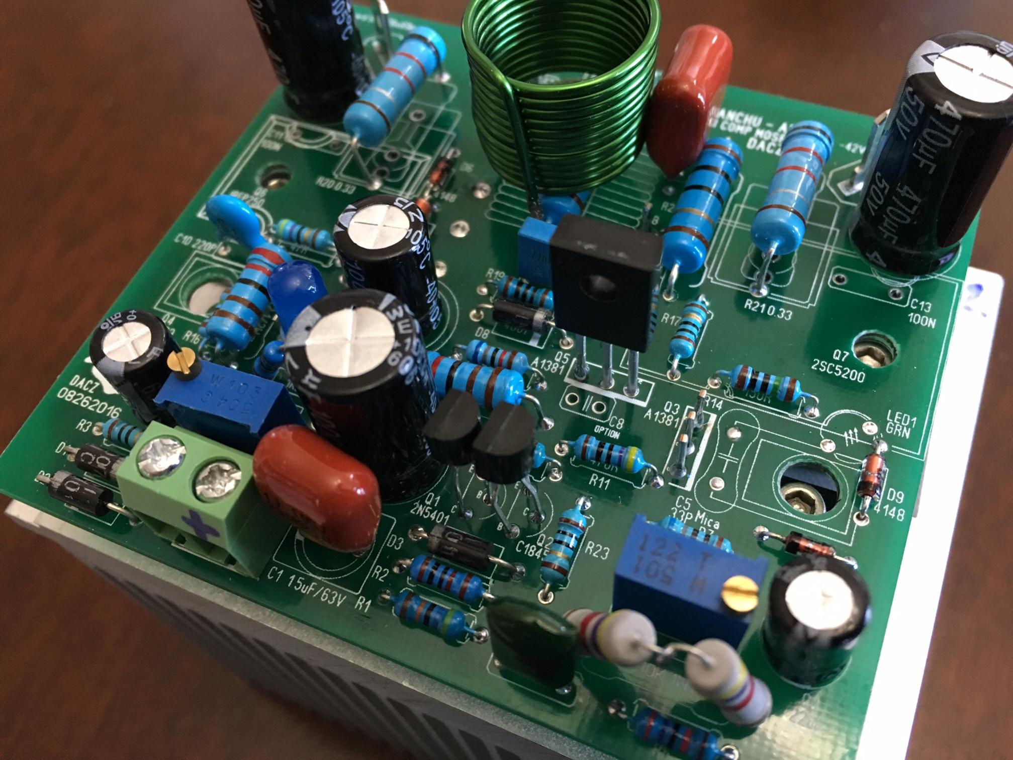
Here is the Aksa/Ranchu quasi amp in Dacz layout. A beautiful sounding amp and 100% AliExpress sourced (except for heatsink (Dell Pentium CPU cooler and PCB from PCBway.com, also in China).
Last edited:
CFH9
Now i can't believe that is something to do with oscillations .
100nf parallel to 2200uf removed.
Capacitors parallel to feedback electrolytics removed.
One pair of output fets removed.
A separate 100uf//47nf for each fet installed directly on fet pin.
Zobel removed.
Rails has been traced again,using analog and digital scope.
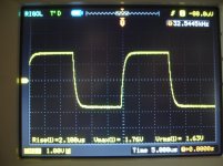
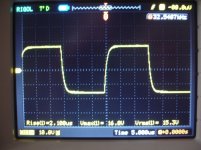
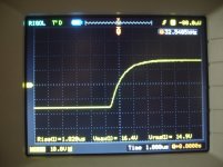
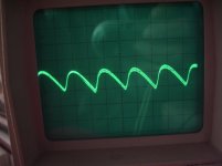
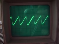
32 KHz square wave 15v RMS ,i cant see something wrong😕
Then putting the scope between power GND on board and signal GND...clear visible sinusoidal.Exactly what the input signal is but at a lower level.It is 15mV when output is 2V.
Pictures,1,2,3 32KHz
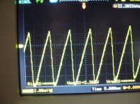
>> 4,5 The rails
>> 6.7 The rails
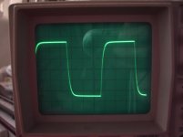
Picture 8, 15V RMS 32KHz
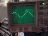
Picture 9 The probe between POWER GND & SIGNAL GND on the board.
Now i can't believe that is something to do with oscillations .
100nf parallel to 2200uf removed.
Capacitors parallel to feedback electrolytics removed.
One pair of output fets removed.
A separate 100uf//47nf for each fet installed directly on fet pin.
Zobel removed.
Rails has been traced again,using analog and digital scope.
32 KHz square wave 15v RMS ,i cant see something wrong😕
Then putting the scope between power GND on board and signal GND...clear visible sinusoidal.Exactly what the input signal is but at a lower level.It is 15mV when output is 2V.
Pictures,1,2,3 32KHz
>> 4,5 The rails
>> 6.7 The rails
Picture 8, 15V RMS 32KHz
Picture 9 The probe between POWER GND & SIGNAL GND on the board.
Attachments
-
 DSC08649.jpg297.6 KB · Views: 270
 -
 DSC08651.jpg307.1 KB · Views: 265
 -
 DSC08654.jpg290.4 KB · Views: 293
 -
 DSC08656.jpg312.6 KB · Views: 97
 -
 DSC08665.jpg309.1 KB · Views: 96
 -
 DSC08676.jpg244.1 KB · Views: 104
 -
 DSC08671.jpg234.3 KB · Views: 92
 -
 DSC08670.jpg236.4 KB · Views: 88
 -
 DSC08667.jpg236.9 KB · Views: 97
Last edited:
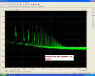
This one looks good.
Now the task is to understand what caused all that garbage we've seen before.
I recommend to put things back, one at a time, checking the rails every time.
Now the task is to understand what caused all that garbage we've seen before.
I recommend to put things back, one at a time, checking the rails every time.
Ah Valery i didn't say that problem is gone.This one looks good.
Now the task is to understand what caused all that garbage we've seen before.
I recommend to put things back, one at a time, checking the rails every time.
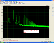
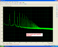
FFT is exactly the same as before!
Last edited:
OK, however we definitely don't see all that HF garbage, which is a step ahead.
Now it doesn't make sense to run the signal until you see a normal FFT picture (in terms of hum).
Now it doesn't make sense to run the signal until you see a normal FFT picture (in terms of hum).
Nice detective work Thimios. 15mV between signal and power ground is bad of course. Would a thick 12ga solid copper wire (or two) soldered between the two be enough to remove that ground loop?
Now i can't believe that is something to do with oscillations .
100nf parallel to 2200uf removed.
Capacitors parallel to feedback electrolytics removed.
One pair of output fets removed.
A separate 100uf//47nf for each fet installed directly on fet pin.
Zobel removed.
Rails has been traced again,using analog and digital scope.
32 KHz square wave 15v RMS ,i cant see something wrong😕
Then putting the scope between power GND on board and signal GND...clear visible sinusoidal.Exactly what the input signal is but at a lower level.It is 15mV when output is 2V.
Pictures,1,2,3 32KHz
>> 4,5 The rails
>> 6.7 The rails
Picture 8, 15V RMS 32KHz
Picture 9 The probe between POWER GND & SIGNAL GND on the board.
Congrats! It's clean.

But if you are shorting the 10R lift resistor then the sinusoidal shouldn't be there. There should be 0V if the signal ground header is connected to ground.
If 10 ohm is shorted, than it's clearly a grounding issue. Additional ground wire and probably more decoupling will help.
No it is shorted!Is the lifted ground resistor (10 ohm) not shorted now?
Now i can't believe that is something to do with oscillations .
100nf parallel to 2200uf removed.
Capacitors parallel to feedback electrolytics removed.
One pair of output fets removed.
A separate 100uf//47nf for each fet installed directly on fet pin.
Zobel removed.
Rails has been traced again,using analog and digital scope.
32 KHz square wave 15v RMS ,i cant see something wrong😕
Then putting the scope between power GND on board and signal GND...clear visible sinusoidal.Exactly what the input signal is but at a lower level.It is 15mV when output is 2V.
Pictures,1,2,3 32KHz
>> 4,5 The rails
>> 6.7 The rails
Picture 8, 15V RMS 32KHz
Picture 9 The probe between POWER GND & SIGNAL GND on the board.
Only after you have debugged problem I remember.
Borys made good suggestion, how to lift input gnd on CFA amps in 100W Ultimate Fidelity Amplifier thread.
Ok Shaan i will do😉Hi thimios.
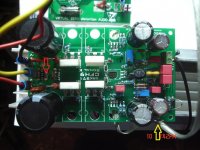
Try disconnecting the ground wire at the yellow arrow from main PSU ground and connect it to the ground at red arrow. Then check the FFT with inputs shorted and open.
Give me 10'.
No it is shorted!
It's not shorted enough if 15mV delta exists!
It's not shorted enough if 15mV delta exists!
No it's no so simple😉
Shaan what you ask about.
Attachments

Last edited:
- Home
- Amplifiers
- Solid State
- CFH7 Amp