2.7mA, 36mA and 104mA seems acceptable
and they are symmetrical, (surprisingly so considering 1% resistors).
Why are you doubting them?
and they are symmetrical, (surprisingly so considering 1% resistors).
Why are you doubting them?
Can someone check these measurements?
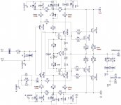
Protection diodes (DZ1/D1 and DZ2/D2) are in wrong direction
in this schematic.
Turn D1 and D2 by 180 degrees.
This mistake has been present in several X's schematics, time to get it right.
I hope that is ok now.
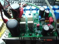
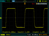
One channel on the test bed.
Power supply +/-44v
Iddle current=100mA
Offset=0mV.
One channel on the test bed.
Power supply +/-44v
Iddle current=100mA
Offset=0mV.
Attachments
-
 sch cfh9.1 measurements.JPG226.3 KB · Views: 358
 -
 DSC08579.jpg297.4 KB · Views: 354
 -
 DSC08580.jpg308.9 KB · Views: 322
 -
 50K SQ R.PNG14.8 KB · Views: 111
 -
 32K SQ R.PNG15.6 KB · Views: 122
 -
 20K SQ R.PNG15.2 KB · Views: 127
 -
 20K CLIP R.PNG18.5 KB · Views: 113
 -
 10K SQ R.PNG15 KB · Views: 109
 -
 1K 22V.PNG18.6 KB · Views: 288
 -
 1K R.PNG15.9 KB · Views: 316
Last edited:
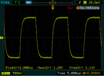
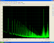
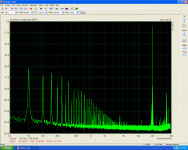
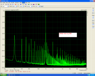
But the good things stop here.
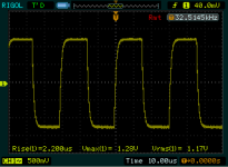
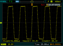
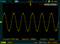
It is a clear audible hum as you can see at all graphs.
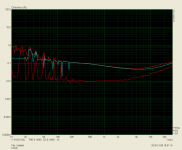
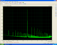
It isn't a power supply problem,the same power supply has been used for two other amplifiers test and all is good( look the last picture as example,it is the PeeCeeBee) using the same power supply and the same test setup.
It is a clear audible hum as you can see at all graphs.
It isn't a power supply problem,the same power supply has been used for two other amplifiers test and all is good( look the last picture as example,it is the PeeCeeBee) using the same power supply and the same test setup.
Attachments
Last edited:
why do you observe so much noise Thimios? can you get to the bottom of it?
will lifting i/p gnd help here, or is it already lifted?
will lifting i/p gnd help here, or is it already lifted?
Last edited:
Hi Prasi,
About all that does is increase the stuffing cost of the board, and add to the cost of the BOM. There is zero benefit in doing that.
-Chris
Yes Chris, it sure does... when i didnt know much abt zobels, i waited 3 full days to get the components for the VSSA....
That is the problem prasi,i don't know why this occur😕why do you observe so much noise Thimios? can you get to the bottom of it?
Hi Thimios,
Thanks for building and testing. It's a strange result and I am not sure what is causing the hum you hear. What is the measured ripple in mV with amp at quiescent current?
This amp should be fairly quiet.
Thanks for building and testing. It's a strange result and I am not sure what is causing the hum you hear. What is the measured ripple in mV with amp at quiescent current?
This amp should be fairly quiet.
Might be worth looking at with a high frequency scope (preferably analog, to avoid being fooled). My guess is that something is oscillating.
Hi X, if you mean the power supply ripple i will try to measure it tomorrow.Hi Thimios,
Thanks for building and testing. It's a strange result and I am not sure what is causing the hum you hear. What is the measured ripple in mV with amp at quiescent current?
This amp should be fairly quiet.
Two other amplifiers has been tested to be sure that power supply is clear enough and everything is ok(see the PeeCeeBee) in previous last picture.
This is that i have in mind but looking with a 100Mz scope i didn't see something.Might be worth looking at with a high frequency scope (preferably analog, to avoid being fooled). My guess is that something is oscillating.
The zobel resistor is cold too.😕
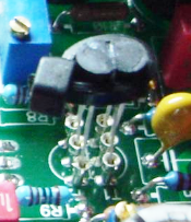
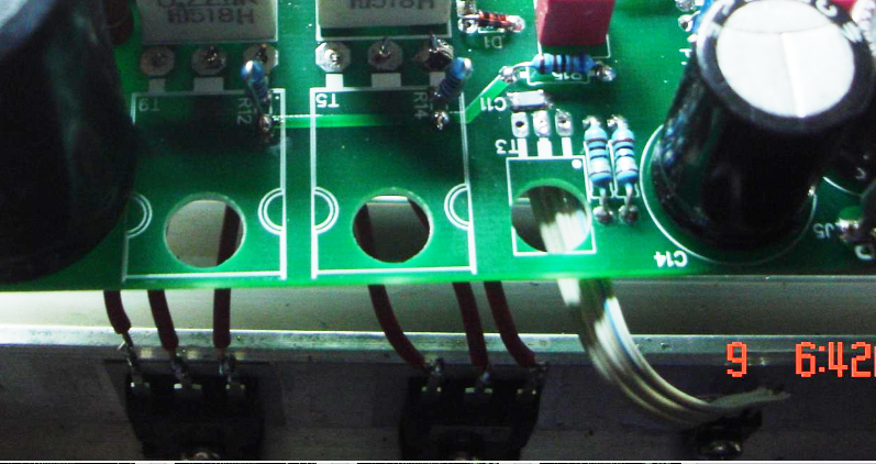
Seems has physical layout differences compared xrk971 build in having flexible sockets for input pair and extended wires for vas and output devices, on the other hand regarding lab tests xrk971 benched squarer waves too but isn't this one the only one being spectrum tested.
Attachments


Last edited:
Thanks for the sharp eyes Byrtt. I think it may make a difference if transistors not soldered on directly. The flying leads don't help and may be picking up hum. Is there a reason the parts are not soldered directly? Also D1 looks like it may not be soldered yet.
Thanks for the sharp eyes Byrtt. I think it may make a difference if transistors not soldered on directly. The flying leads don't help and may be picking up hum. Is there a reason the parts are not soldered directly? Also D1 looks like it may not be soldered yet.
I Agree with that!
Out of experience at my Aleph X amp.
To one channel I added 2" wires for better heat spreading.. I could not believe it is the same amplifier even do I compared the L to R channel.
Please at least use solid core wire if you can not mount the (power) mosfets direct into the PC boards as last solution..
Hello All,
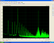
This looks like catching a rather strong EMF from the transformer or power line. Rails ripple is normally 100Hz (bridged rectifier), but here the dominant is 50Hz, so the amp is catching the mains sine directly somehow.
And then it inter-mpdulates with the test signal, creating myriads of components all over the place.
Thimios, can you please show what it looks like with the input shorted.
Thanks for the sharp eyes Byrtt. I think it may make a difference if transistors not soldered on directly. The flying leads don't help and may be picking up hum. Is there a reason the parts are not soldered directly? Also D1 looks like it may not be soldered yet.
The reason for non directtly soldering is that heatshink not match.I have do the same with Sons vhex tested here http://www.diyaudio.com/forums/solid-state/294632-sons-vhex-32.htmlI Agree with that!
Out of experience at my Aleph X amp.
To one channel I added 2" wires for better heat spreading.. I could not believe it is the same amplifier even do I compared the L to R channel.
Please at least use solid core wire if you can not mount the (power) mosfets direct into the PC boards as last solution..
Di is soldered.
There are solid core wires.
I will try to find a different heatsink and i will repeat the test when this done.
Thanks for reply.
Hi Valery i will try your suggestion soon.Hello All,
This looks like catching a rather strong EMF from the transformer or power line. Rails ripple is normally 100Hz (bridged rectifier), but here the dominant is 50Hz, so the amp is catching the mains sine directly somehow.
And then it inter-mpdulates with the test signal, creating myriads of components all over the place.
Thimios, can you please show what it looks like with the input shorted.
The same power supply has been tested using two other amplifiers, the same day, without any problem.See the PeeCeeBee in the last picture post#565Hi Valery i will try your suggestion soon.
The supply is fine, but seeing the output spectrum with the input shorted may give us a clue where to look next.
- Home
- Amplifiers
- Solid State
- CFH7 Amp