Andrewlebon,
I don't know - I have never built the FH11. I still need to listen to the CFH9 in stereo before I can give a fair assessment. The CFH9 is a CFA amp - so I expect it to sound different. I guess I need you to make the CFH9 and then you can tell me? The FH11 is currently one of your favorite amps, no?
I don't know - I have never built the FH11. I still need to listen to the CFH9 in stereo before I can give a fair assessment. The CFH9 is a CFA amp - so I expect it to sound different. I guess I need you to make the CFH9 and then you can tell me? The FH11 is currently one of your favorite amps, no?
Solidly mounted to heatsink now. Offset is stable to 5mV after warmed up. Bias is stable and set currently at 150mA. Heatsink is not too warm at all. Sounds really nice. Super easy to make and parts are not expensive at all. Great amp. Nice deep bass, smooth mids and clear highs.
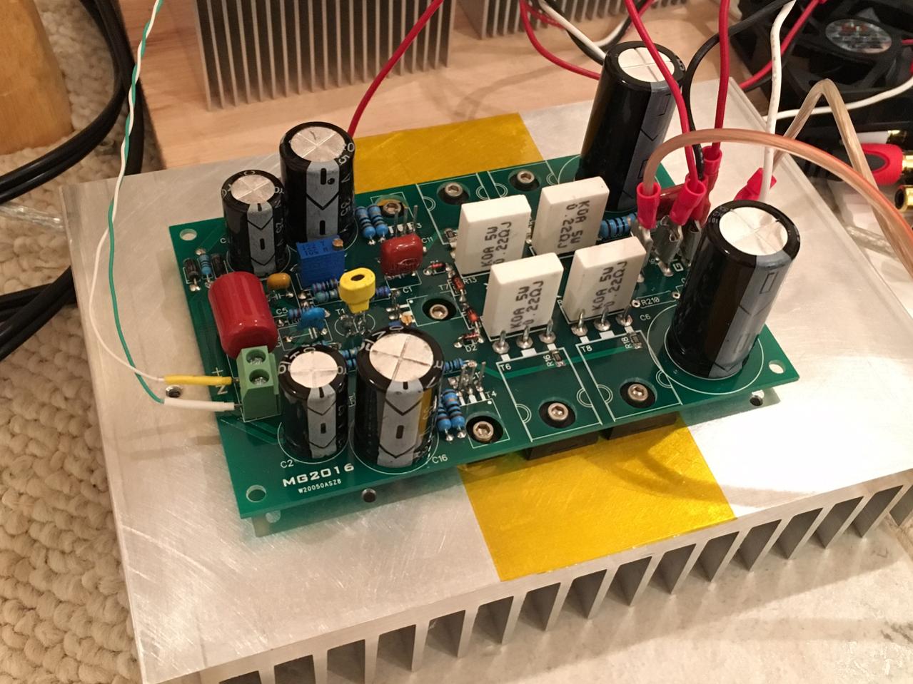
Note that bias current is monitored via output and Source pin sticking up from one of the MOSFETs. Be careful not to short the pins with the alligator clip.
Note that bias current is monitored via output and Source pin sticking up from one of the MOSFETs. Be careful not to short the pins with the alligator clip.
Attachments
Last edited:
Thanks Sonal for posting the PDF's. I sort of wished my boards had on board inductor. There is certainly room.
Looking good XRK !
Seem like you used some low inductance resistors in the OPS.
I happen to have those - did not know they were low inductance units. I normally use 2w or 3w metal thin film ones here but Marc had it drawn for small stand up rectangular resistors.
Yes X,
MPC71 are low inductance resistors, and they have a frendly parttern and price i find. You can find then under fukushima brand...
Marc
MPC71 are low inductance resistors, and they have a frendly parttern and price i find. You can find then under fukushima brand...
Marc
Thanks Sonal for posting the PDF's. I sort of wished my boards had on board inductor. There is certainly room.
X,
As a newbie to building:
Where do you have your inductor/zobel network mounted off board.????
Can we drill holes for inductor on the GB pcbs ordered.?????
Myles
X,
As a newbie to building:
Where do you have your inductor/zobel network mounted off board.????
Can we drill holes for inductor on the GB pcbs ordered.?????
Myles
I think AndrewT suggested outboard mounting even at the speaker terminals. 1.0 to 1.2uH and 10R 2W in parallel. You could also crimp one to a female spade connector and have it sticking vertically up like a spiral helix from PCB.
More testign today - DC offset is excellent - only 3mV drift today when turned on and warmed up.
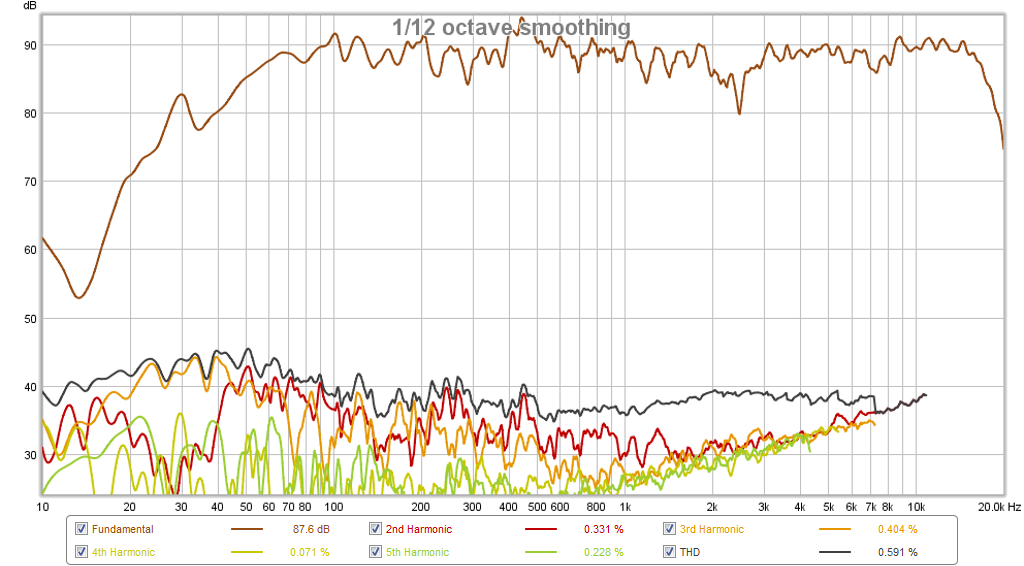
Love the sound. Quick measurement with my 10F/RS225 FAST speaker shows no abnormal distortions - very clean.
Attachments
Last edited:
Hi X,
thats very good news. I will dismantel damaged Nbip board from case and will finished MDF case for CFH9.
Marc
thats very good news. I will dismantel damaged Nbip board from case and will finished MDF case for CFH9.
Marc
Thanks X,
Since I will not be building this amp for a little while, I will see how other people mount the inductor/resistor pair.
Where did you mount yours????
Myles
Since I will not be building this amp for a little while, I will see how other people mount the inductor/resistor pair.
Where did you mount yours????
Myles
I currently am not running an inductor yet. I will see what I can throw together and mount from a spade quick connect.
Mointing the inductor outboard is not really an issu and if you don't want to mount it in "tube amp style" you can use a piece of breadboard.
Marc
Marc
CFH9 BOM
As built BOM and setup instructions attached.
As built BOM and setup instructions attached.
Just arrived in mail. They look good.
Made using Gerbers from here:
http://www.diyaudio.com/forums/solid-state/294834-cfh7-amp-40.html#post4876223
Schematic:
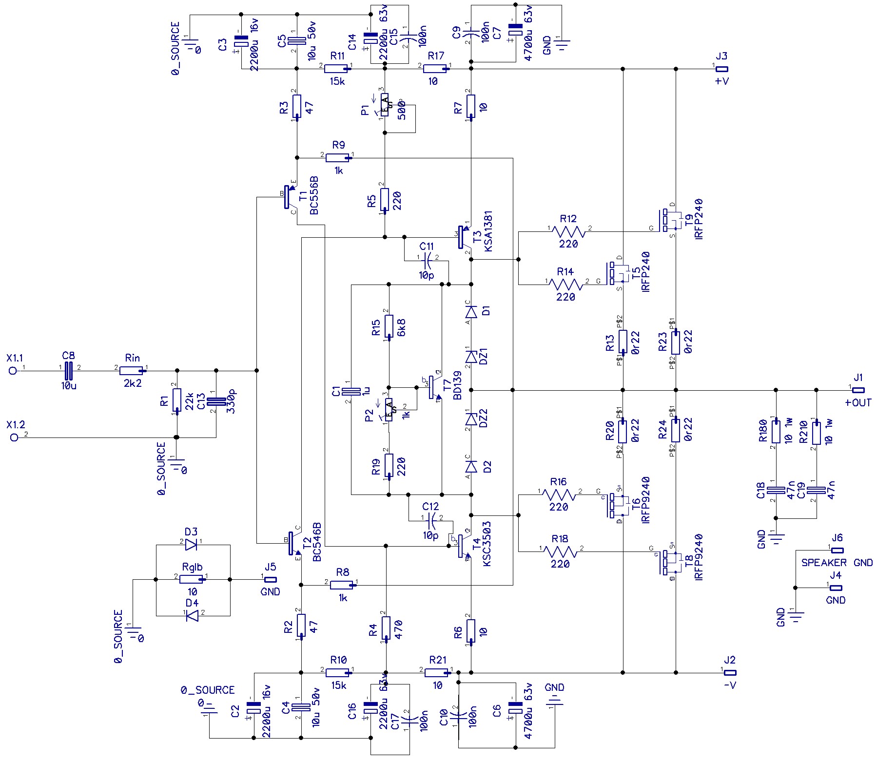
Parts placement:

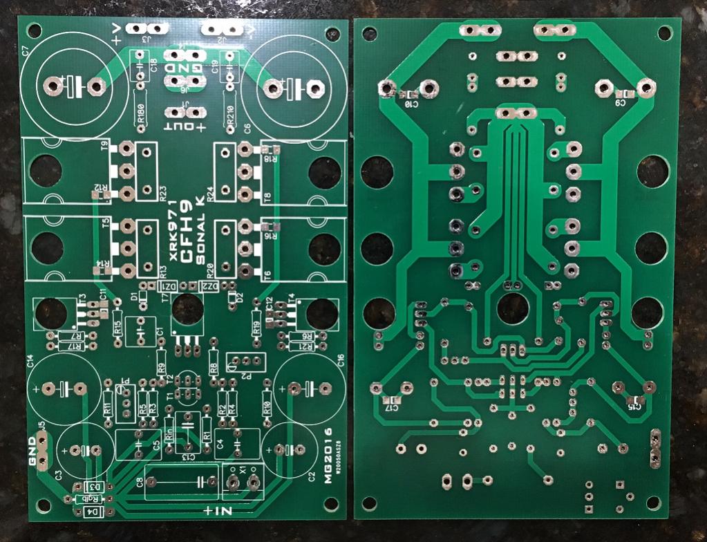
I don't have a BOM yet but imagine it's very similar to the one I posted earlier with exception for SMT parts for 220R gate stoppers and 100nF bypass caps. I am not sure if the part designations are the same though so you will have to look at the schematic above to figure out.
Attachments
Last edited:
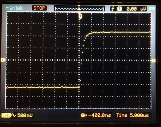
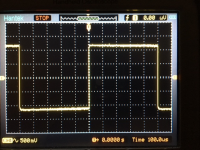
I was able to borrow a friend's Hantek DSO 1200 scope.
The 1kHz square wave looks good. I didn't have any 10pF NP0 SMT caps so am using 22pF, and so the edge might even be sharper. Right now 1/e risetime is about 1.5usec - still not bad. Very clean, no ringing or overshoot. I used the 1kHz test signal from the oscope through a 10:1 voltage divider to generate the square wave. I don't have a function generator. Load is an 8R 25w resistor.
1kHz signal measured across load resistor:

zoomed in:
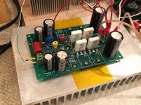
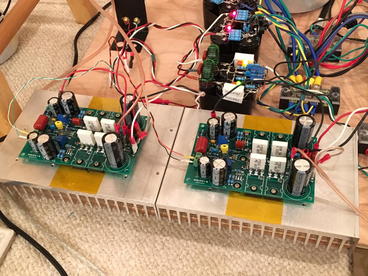
I am pretty sure all the folks in the GB are going to like this amp. Performs very well. I just mounted the second channel on heatsink and tested it - fired right up no issues.
The 1kHz square wave looks good. I didn't have any 10pF NP0 SMT caps so am using 22pF, and so the edge might even be sharper. Right now 1/e risetime is about 1.5usec - still not bad. Very clean, no ringing or overshoot. I used the 1kHz test signal from the oscope through a 10:1 voltage divider to generate the square wave. I don't have a function generator. Load is an 8R 25w resistor.
1kHz signal measured across load resistor:
zoomed in:
I am pretty sure all the folks in the GB are going to like this amp. Performs very well. I just mounted the second channel on heatsink and tested it - fired right up no issues.
Attachments


- Home
- Amplifiers
- Solid State
- CFH7 Amp