I am beginning to prefer the 1 stage CFA approach , simple ... no servo, nothing to "slow it down" (500V/uS) 😀 .
OS
Finally recognized.

OS build one and listen, maximal insight into recordins.


Thanks OS,
And believe me I don't underestimate what 90 watts can do. My H/K integrated is rated about 90 per channel and that through a passive xo and driving both devices the full range will drive you out of the room no problem. But my driver is only going down to 35hz, not bad for a 6 1/2" speaker with 1.25" p to p excursion. Haven't needed to add any sub at this point, maybe for movies it would come in handy.
And believe me I don't underestimate what 90 watts can do. My H/K integrated is rated about 90 per channel and that through a passive xo and driving both devices the full range will drive you out of the room no problem. But my driver is only going down to 35hz, not bad for a 6 1/2" speaker with 1.25" p to p excursion. Haven't needed to add any sub at this point, maybe for movies it would come in handy.
OS -- this is the next step... towards the Simplified CFA topology. Now that we know what the Classic topology is and does and how and why --- Try various simplified versions next and see if there is also an optimum version to be found.
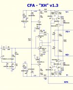
The basic circuit topology looks like this --
View attachment Simplified CFA.pdf
THx-RNMarsh
The basic circuit topology looks like this --
View attachment Simplified CFA.pdf
THx-RNMarsh
Last edited:
I actually "discovered" that (CM -VAS) a while back. I was looking for THD/slew
... overlooked the (I) stability factor 😱
As far as the floating mirrored IP stage ...(with the caps) , you don't have much
offset drift to begin with.
Reaching the optimum component/performance/stability with this
particular "simple" topology has eluded me slightly. The shunt
comp. definitely put it "over the threshold.
As I said before , I have nothing else in the "bag o' tricks" that
will do 10ppm and be this simple and stable.
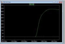
At 10p/22k shunt , the sim says 50V in .05uS (1 kv !) of course , with the input filter and a non- ringing output, 300-400v is enough ... but it CAN do it (1k).
NO other sim can go that fast 😀. I like - (it simple).
PS - builders have said that faster sounds better , who am I to argue ?
This does seem to be as close to the "base" CFA concept as one can get.
Edit - one builder said this 1 stage IP pair may get a little "warm" ... careful
choice of a more robust to-92L (800ma) pair might be better for high output use.
OS
... overlooked the (I) stability factor 😱
As far as the floating mirrored IP stage ...(with the caps) , you don't have much
offset drift to begin with.
Reaching the optimum component/performance/stability with this
particular "simple" topology has eluded me slightly. The shunt
comp. definitely put it "over the threshold.
As I said before , I have nothing else in the "bag o' tricks" that
will do 10ppm and be this simple and stable.
At 10p/22k shunt , the sim says 50V in .05uS (1 kv !) of course , with the input filter and a non- ringing output, 300-400v is enough ... but it CAN do it (1k).
NO other sim can go that fast 😀. I like - (it simple).
PS - builders have said that faster sounds better , who am I to argue ?
This does seem to be as close to the "base" CFA concept as one can get.
Edit - one builder said this 1 stage IP pair may get a little "warm" ... careful
choice of a more robust to-92L (800ma) pair might be better for high output use.
OS
Attachments
Last edited:
Yup - I'm on the PCB now !
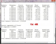
(below) is the optimum circuit.
below 2 is 1k
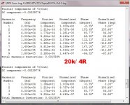
below 3 is 20k.
On both , first 4 harmonics thd IS nearly the same as
all 9. This must mean almost NO H5 + .
5 ppm at 1k/ 100v p-p is really good for this simplicity level. 😎
OS
(below) is the optimum circuit.
below 2 is 1k
below 3 is 20k.
On both , first 4 harmonics thd IS nearly the same as
all 9. This must mean almost NO H5 + .
5 ppm at 1k/ 100v p-p is really good for this simplicity level. 😎
OS
Attachments
OS,
Define a little bit warm, and would this mean you would want to mount those devices on the main heatsink if possible?
Will thimios have one of these built by morning! 😀
Define a little bit warm, and would this mean you would want to mount those devices on the main heatsink if possible?
Will thimios have one of these built by morning! 😀
Last edited:
5 ppm at 1k/ 100v p-p is really good for this simplicity level. 😎
OS
Modulation/subtraction on the same part has a great deal with this low ppm/speed. If the rest of the circuit can follow and in this case obviously can, then a little has left to improve such high performance input/VAS stage.
Will try and compare with FO, normally with mine OPS.
Yup - I'm on the PCB now !
(below) is the optimum circuit.
In order to improve noise performance I would lower R2 to 10-22 k and decouple D3, D4 since they have quite high inherent noise voltage. 😉
OS,
Define a little bit warm, and would this mean you would want to mount those devices on the main heatsink if possible?
Will thimios have one of these built by morning! 😀
The input transistors change input voltage to current. If feedback resistor is low enough the current modulation will be high. You can burn the transistors if use high voltage power supply 😱
As OS said, in some condition (low feedback resistance and high voltage power supply) it should use high current TO-92 device for input transistors. Or we can cascode it or use resistor to limit collector voltage, and power dissipation will be decrease.
Thanks Bimo,
I assumed that the heat could be limited by voltage or in ways you just posted, just wondered if it would help to mount these devices to a heat sink.
I assumed that the heat could be limited by voltage or in ways you just posted, just wondered if it would help to mount these devices to a heat sink.
Thanks Bimo,
I assumed that the heat could be limited by voltage or in ways you just posted, just wondered if it would help to mount these devices to a heat sink.
It is difficult to find heat sink for TO-92 device. Or you can make it your self, but I can not....
Finally recognized.
OS build one and listen, maximal insight into recordins.
All classic CFA's are 1 gain stage amplifiers - with or without a buffer infront of the level shifter.
OS -- this is the next step... towards the Simplified CFA topology. Now that we know what the Classic topology is and does and how and why --- Try various simplified versions next and see if there is also an optimum version to be found.
The basic circuit topology looks like this --
View attachment 413974
THx-RNMarsh
Just make sure you drive it with a decent signal source since its unbuffered!
Could you show some simulated data, distortion, loop gain, square wave...?
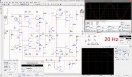
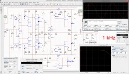
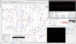
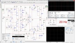
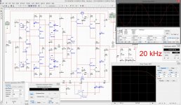
OK, here are some simulations:
4 pictures with sine wave 20Hz, 1kHz, 20kHz, 50kHz
4 pictures with square - same 20Hz, 1kHz, 20kHz, 50kHz
1 picture with 1 kHz spectrum
1 picture with open loop (no compensation either)
It will be possible to audition the prototype open loop - linear enough for decent sound 😉
Attachments
-
 01-20hz-sn.jpg952.9 KB · Views: 287
 -
 02-1khz-sn.jpg962.7 KB · Views: 244
 -
 07-20khz-sq.jpg961.5 KB · Views: 111
 -
 06-1khz-sq.jpg952.1 KB · Views: 121
 -
 05-20hz-sq.jpg957.4 KB · Views: 202
 -
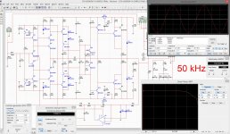 04-50khz-sn.jpg974 KB · Views: 200
 -
 03-20khz-sn.jpg962.5 KB · Views: 220
 -
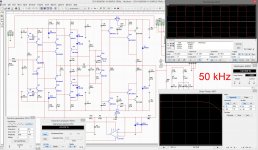 08-50khz-sq.jpg957.1 KB · Views: 118
 -
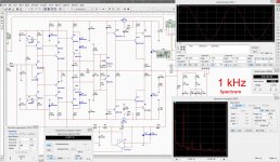 09-1khz-sp.jpg956.7 KB · Views: 121
 -
 10-1khz-ol.jpg966.6 KB · Views: 134
It is difficult to find heat sink for TO-92 device. Or you can make it your self, but I can not....
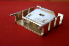
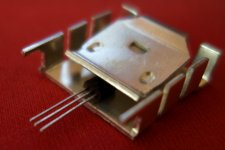
Last summer I've got excellent small aluminium heatsinks from Poland.
Works perfectly with both TO-126 and TO-92.
Strongly recommend something similar...
Attachments
Actually, heat dissipation matter is one of the reasons for using cascoded VAS.
For example, I use 2n5551 as VAS (higher hfe, speed, etc.) and cascode it with MPSA42 - lower "quality" but higher power.
For example, I use 2n5551 as VAS (higher hfe, speed, etc.) and cascode it with MPSA42 - lower "quality" but higher power.
Last summer I've got excellent small aluminium heatsinks from Poland.
Works perfectly with both TO-126 and TO-92.
Strongly recommend something similar...
You might use it for heat sinking 2 transistors to help with thermal drift.
THx-RNMarsh
What are the pro-con for the error correction occurring in the input stage or in the output stage??
THx-RNMarsh
THx-RNMarsh
You might use it for heat sinking 2 transistors to help with thermal drift.
THx-RNMarsh
Yep!
- Home
- Amplifiers
- Solid State
- CFA Topology Audio Amplifiers