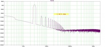
The square wave on the PS is a good idea in that it doesnt use a network analyzer.... any ringing would be used to note the freq of the ringing... the decay rate of any ringing found is determined by the R is the circuit.
_________________________________
Did anyone test their SIM circuit with simulated speaker loads (other than 8/4 Ohms)? Or, measure THD with a real load?
Would you use this circuit for a simple load and see what changed? From D.Self's book -
View attachment SKR Z model.pdf
THx-RNMarsh
_________________________________
Did anyone test their SIM circuit with simulated speaker loads (other than 8/4 Ohms)? Or, measure THD with a real load?
Would you use this circuit for a simple load and see what changed? From D.Self's book -
View attachment SKR Z model.pdf
THx-RNMarsh
Well, I DID say I used a square wave for this test. Yes, you could do a sweep and plot the exact impedance and a bunch of things but none of that will help you actually select the right lytic. It is easier just to observe the ringing directly (with a square wave) and test a number of different lytics across it. You can't necessarily use the ESR values in the datasheet because they aren't specified at 3MHz and they may be max values, not typical values.
Well, I DID say I used a square wave for this test. Yes, you could do a sweep and plot the exact impedance and a bunch of things but none of that will help you actually select the right lytic. It is easier just to observe the ringing directly (with a square wave) and test a number of different lytics across it. You can't necessarily use the ESR values in the datasheet because they aren't specified at 3MHz and they may be max values, not typical values.
Yep.
-RNM
Did anyone test their SIM circuit with simulated speaker loads (other than 8/4 Ohms)? Or, measure THD with a real load?
Would you use this circuit for a simple load and see what changed? From D.Self's book -
View attachment 413155
THx-RNMarsh
???
A comp change the CF of a stage, not his slope. Adding a stage will add a 6dB/oct supplementary filter. Most of the time, they are all near 10 MHz.
I use the term "compensation" to be any part of the design that has to do with stability. A cascode transistor will reduce the pole of the preceeding stage by stopping Miller effect. If this pole was one of the ones that was limiting the amplifier stability, then the amplifier will be able to be made faster with less distortion. Each stage has a source and load impedance where gain and bandwidth are highest, and a stage can be added to get into this optimal range, which can increase the stability of the entire amplifier, even if there are more total poles.
As far as damping rails without lab equipment, I can't think of anything. However those with some empirical experience could make a chart with the most common capacitance values based on simple decoupling layout estimates and someone with just a soldering iron could start with that and tweak by ear.
Regarding the series resistor damping, it makes sense to me that it sounds better, because the inductance of the resistor and the fact that the resistance is much higher than the reservoir practically takes the film decoupling out of the circuit, unless the reservoir is a long ways away. In my experience having a bit more supply inductance is sonically preferable to having resonant bypass (as long as there is no oscillation). However sound focus and imaging seem better if there is no resonance as well as supply inductance being low - but it's harder to get this right.
The square wave on the PS is a good idea in that it doesnt use a network analyzer.... any ringing would be used to note the freq of the ringing... the decay rate of any ringing found is determined by the R is the circuit.
_________________________________
Did anyone test their SIM circuit with simulated speaker loads (other than 8/4 Ohms)? Or, measure THD with a real load?
Would you use this circuit for a simple load and see what changed? From D.Self's book -
View attachment 413155
THx-RNMarsh
Interesting.
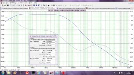
Just ran simulations for 2 amp models - classic VFA and CFA. Both models have live prototypes, so I know they are close to real life.
Tried 4 Ohm resistive load and speaker equivalent you just showed.
With Zobel network attached and without it.
Checked frequency response, phase shift, THD @ 20 kHz.
Practically no change. Zobel influences frequency response over 30-50 kHz.
Changing the load from R to speaker equivalent gives negligible change at even higher frequencies. Within the audio bandwidth - rock solid performance.
But both are good amps. I will try to do the same with something more "simple" later today.
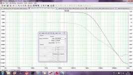
OK great news. It just needed to be done to be complete and sure and know. THx-Richard Marsh
Has anyone here or anywhere at DIYAudio used the AD844? It is a translinear second generation plus type current conveyor (CCII+) followed by a (translinear) voltage buffer?
THx-RNMarsh
THx-RNMarsh
Has anyone here or anywhere at DIYAudio used the AD844? It is a translinear second generation plus type current conveyor (CCII+) followed by a (translinear) voltage buffer?
THx-RNMarsh
I used it extensively in my paX error-correction amplifier published in Elektor 4/2008. It's available for download at the Elektor site. An adapted article has been published by AudioXpress.
Jan
Last edited:
There are some in my system. I preferred OP260, now obsolete ;-(, that i used by thousands in mixing desks for a more optimal feedback resistance value. It is my second choice when i can afford the low Z -input value..Has anyone here or anywhere at DIYAudio used the AD844?
An improved CFA topology ---
View attachment Improved CFOA.pdf
There are also new CFA designs with increased CMRR and, there are fully differential CFA.
THx-RNMarsh
View attachment Improved CFOA.pdf
There are also new CFA designs with increased CMRR and, there are fully differential CFA.
THx-RNMarsh
Last edited:
From - 2013 Analog Circuits and Signal processing:
View attachment AD844-2.pdf
View attachment AD844 comment.pdf
THx-RNMarsh
View attachment AD844-2.pdf
View attachment AD844 comment.pdf
THx-RNMarsh
Does the circuit in post 5777 exist as an opamp??
Looks like a very good circuit for balanced to single ended conversion
Looks like a very good circuit for balanced to single ended conversion
An improved CFA topology ---
View attachment 413231
There are also new CFA designs with increased CMRR and, there are fully differential CFA.
THx-RNMarsh
There are/were a few others. AD846, MAX435/436 and PA603(A) went the way of the dodo.
OPA860 still available.
I think Linear has a chip with a CCII plus a separate opamp, don't remember the #.
Jan
Does the circuit in post 5777 exist as an opamp??
Looks like a very good circuit for balanced to single ended conversion
I dont know... they are published designs. Mostly research papers. ... here as ideas for sim changes/mods to audio amp designs.
-RM
Last edited:
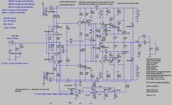
This is with lateral MOSFET OPS and JFET input, not so low distortion, but simpler and according to the simulation very stable.
Damir
Damir
Attachments
- Home
- Amplifiers
- Solid State
- CFA Topology Audio Amplifiers