The usual excuse 😀.
But then I was asking why you think not how you implement such. No schematic is required, just the rationale behind your statement.
One possible reason I can think of, probably totally wrong, is that less devices in loop would make that loop easier to get stable. Not that you can't make a loop with many devices stable, it may just take more effort.
Maybe, with less devices, the loop can be closed at a much high frequency?
One possible reason I can think of, probably totally wrong, is that less devices in loop would make that loop easier to get stable. Not that you can't make a loop with many devices stable, it may just take more effort.
Maybe, with less devices, the loop can be closed at a much high frequency?
You are right, according to Mr. Bode that's totally wrong. It doesn't matter how you dice and splice the available loop gain (global, local, embedded, you name it), the global stability will be (best case) the same. Unless you consider the feedback loop physical length (with the associated parasitic elements) an important criteria worth considering.
But I would not be surprised by this kind of explanation, I've read such nonsense before, like "the global feedback loop is to long, hence the feedback signal is delayed, so it cannot correct properly the distortions".
I understand the concept of feedback but could someone simply tell me what feed forward correction is? How does feeding a signal forward correct an error previous to that if that is what is supposed to happen?
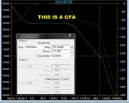
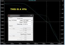
Yet we saw substantial differences in CFA and VFA both in slev-rate, frequency response and phase margins.
Mathematics is only a model of reality.
Mathematics is only a model of reality.
Yet we saw substantial differences in CFA and VFA both in slev-rate, frequency response and phase margins.
Mathematics is only a model of reality.
Those differences are not so great ... I have a 2+ mhz UG-220V/uS VFA.
I will admit it was harder to compensate for that level of performance. 🙁
On the other hand , even as one could design a 3+mhz - 400V/us CFA ,
do you really need that much bandwidth/gain margin for audio ?
Diminishing returns.
OS
VFA/CFA
The line has blurred.
You can get the same performance.
CFA - simpler, but harder to get PSRR-offset under control.
VFA - harder to compensate with an easier offset solution.
More parts !! 🙁
Both are 200+ slew/2mhz UG. Both have a similar gain margin @ 20K (and
low THD).
OS
The line has blurred.
You can get the same performance.
CFA - simpler, but harder to get PSRR-offset under control.
VFA - harder to compensate with an easier offset solution.
More parts !! 🙁
Both are 200+ slew/2mhz UG. Both have a similar gain margin @ 20K (and
low THD).
OS
Attachments
Yet we saw substantial differences in CFA and VFA both in slev-rate, frequency response and phase margins.
Mathematics is only a model of reality.
No, no and no - if one cares to compare apples to apples.
Yes, the best we have.
Now, care to answer my question? If you don't feel like, that's ok.
new Direction --
If it is harder to stablize in SIM, I found it even harder to do in real physical ciircuits.
In 'practice' the CFA always was a piece of cake to have stable. No messing with complex schemes were necessary.... and which inevitably needs some fudging to work in practice.
There is no difference in complexity to dc servo either IMO.
And simpler circuits for equivalent performance were also easy to stabilize.
One direction from here is -- Cancellation techniques use new concepts and can be simple as you like.
This is not just about-- is it audible? That question is another forum somewhere. This is about designers and designing electronic amplifying circuits. SOTA circuits. And, power amps in particular.... to At Least keep pace with digital designs.
Another direction to go is to perfecting a "Simplified" CFA topology..... or the Compli Push pull topology.
THx-RNMarsh
.
The line has blurred.
You can get the same performance.
CFA - simpler, but harder to get PSRR-offset under control.
VFA - harder to compensate with an easier offset solution.
More parts !! 🙁
Both are 200+ slew/2mhz UG. Both have a similar gain margin @ 20K (and
low THD).
OS
If it is harder to stablize in SIM, I found it even harder to do in real physical ciircuits.
In 'practice' the CFA always was a piece of cake to have stable. No messing with complex schemes were necessary.... and which inevitably needs some fudging to work in practice.
There is no difference in complexity to dc servo either IMO.
And simpler circuits for equivalent performance were also easy to stabilize.
One direction from here is -- Cancellation techniques use new concepts and can be simple as you like.
This is not just about-- is it audible? That question is another forum somewhere. This is about designers and designing electronic amplifying circuits. SOTA circuits. And, power amps in particular.... to At Least keep pace with digital designs.
Another direction to go is to perfecting a "Simplified" CFA topology..... or the Compli Push pull topology.
THx-RNMarsh
.
Last edited:
The line has blurred.
You can get the same performance.
CFA - simpler, but harder to get PSRR-offset under control.
VFA - harder to compensate with an easier offset solution.
More parts !! 🙁
Both are 200+ slew/2mhz UG. Both have a similar gain margin @ 20K (and
low THD).
OS
OS, I see that you still use simple Middlebrook probe for CFA. I suggest that you switch to Tian probe(LTspice education library, LoopGain2), much more accurate specially for CFA.
Damir
Waly
If we look a compensation schemes like TMC or Cherry then you clearly see the most profound performance differences in those schemes in the high swing and high frequency range. What these "different schemes does it that they partially close the loop over fewer devices or stages, improving higher frequency performance. This is the intellectual logic that makes me believe in closing loops over fewer "stages or devices" is beneficial.
If we look a compensation schemes like TMC or Cherry then you clearly see the most profound performance differences in those schemes in the high swing and high frequency range. What these "different schemes does it that they partially close the loop over fewer devices or stages, improving higher frequency performance. This is the intellectual logic that makes me believe in closing loops over fewer "stages or devices" is beneficial.
Waly
If we look a compensation schemes like TMC or Cherry then you clearly see the most profound performance differences in those schemes in the high swing and high frequency range. What these "different schemes does it that they partially close the loop over fewer devices or stages, improving higher frequency performance. This is the intellectual logic that makes me believe in closing loops over fewer "stages or devices" is beneficial.
 Compensation can (but not necessary) involve feedback. Example: Miller compensation vs. shunt compensation. I don't see any intellectual logic here.
Cherry and other nested feedback types are mostly frequency-dependant feedback based, compensations around a smaller portion of the circuit. Again this advocates that feedback around fewer stages brings benefits, Fine with me that you don't see it this way, for me it's quite obvious, This is also what I see in my simulations and hopefully soon in IRl. So far my designs has proved to be quite similar to my sim findings.
No according to feedback theory's adapted model of the real world it would not matter, but but then again theory is exactly that, an ideal adaption of the real-world deliberately omitting detailing elements from the real world. While my background is not electrical, I have performed enough of military (F16) mechanical FEA work to know the physical limitations of mathematical models.
Maybe since you hold all the answers you would care to join a fruitful discussion on how to bring designs to a new level. Making the same as we have for the last 30 years does not really bring us forward, bu hey maybe that's the thing all circuits sound the same if the have similar spec's.. Or is the music performance only of academic value to you. As long as the distortion is low, who cares about the music...??
Maybe since you hold all the answers you would care to join a fruitful discussion on how to bring designs to a new level. Making the same as we have for the last 30 years does not really bring us forward, bu hey maybe that's the thing all circuits sound the same if the have similar spec's.. Or is the music performance only of academic value to you. As long as the distortion is low, who cares about the music...??
OS, I see that you still use simple Middlebrook probe for CFA. I suggest that you switch to Tian probe(LTspice education library, LoopGain2), much more accurate specially for CFA.
Damir
I could , but middlebrook serves me well.
The reasons for the Tian are apparent ... Plotting Loop Gain Using the Tian Method - Spring 2011
I am more "cause and effect" ... I'll get lazy and just .step a range of
values. Hit the circuit with a square wave to see the pretty ringing 😀 .
You notice ... all my creations work first time with no fuss. I will even
throw the variables of the real world OEM examples into my design ,
if similar.
I notice you are going for more "exotic" comp. schemes. I try to avoid
these.. as some of my builders have sourcing issues.
If I run into a tight corner ... I will use it (your cherry comp.) 😀 .
OS
OS, I see your reason, but with CFA where feedback impedance are low it is important to have a current probe together with a voltage probe.
It is simple to use it, put a text "-1/(1-1/(2*(I(Vi)@1*V(x)@2-V(x)@1*I(Vi)@2)+V(x)@1+I(Vi)@2))" into schematic under simulation, do .ac(with tian probe) and plot, let say, vout, then change it to that text.
DAmir
Hi Richard,
I actually met and talked with the Benchmark guy at RMAF 2013. He gave me the patent numbers for the circuit and they are still on my list of things to look up. He said the patents were by THX. Very interesting story, but I don't know much more. Nice that they had the stones to include a clipping indicator. Yeah!!
Cheers,
Bob
A clipping indicator is too little too late IMO
Because,all THX recordings are digital these days and therefore hard limited.
A clipping indicator is too little too late IMO
Because,all THX recordings are digital these days and therefore hard limited.
Why? does THX prescribe hard clipping? and does adding an other layer of clipping no additional damage? and don't I (and others) listen to analog sources?
Why? does THX prescribe hard clipping? and does adding an other layer of clipping no additional damage? and don't I (and others) listen to analog sources?
Translation - nothing above 0dBFS is possible in digital recordings. In pure theory some filter overshoot of several samples close to FS is possible at analog output.
Translation - nothing above 0dBFS is possible in digital recordings. In pure theory some filter overshoot of several samples close to FS is possible at analog output.
Translation of what?!!! this is about an amplifier having a clipping indicator and someone stating that the clipping indicator is not very useful due to the fact that we use digital sources or, in other words, due to the fact that the material is 'hard'-clipped anyway.
I really do not understand a response like yours, this is about amps not the source, and the amp has the clipping indicator, not the digital source. Yes I do understand that! don't you?
The post also noted that this all (the clipping (including the 'hard'-clipping)) due to THX. My question was 'Why?'. Why is this due to THX, why is it not good to have a measure to prevent (by lowering the average output power of the amp) clipping (of the amp not the source).
Last edited:
The "someone" is quite right in case we know digital source analog output level and amplifier gain, we may set it to prevent clipping in any case.
- Home
- Amplifiers
- Solid State
- CFA Topology Audio Amplifiers