Have we explored the OPS biasing concepts here from Class-B output stage with feedforward.
Excellent stuff from a long time great thinker in audio. All Great stuff on his site... all good - only con is in omission or holes that he hasnt covered completely. [who could?]
THx-RNMarsh
Excellent stuff from a long time great thinker in audio. All Great stuff on his site... all good - only con is in omission or holes that he hasnt covered completely. [who could?]
THx-RNMarsh
Last edited:
Go on. Post it. There are loads amps on this forum with zillion devices. Though some have better THD than yours, anything new is worth looking at. eg how you achieve the zillion V/us slewThree days later, I guess everybody now understands why I am not posting the schematics.
Much more interesting (cos not Unobtainium) would be your schematic.Perhaps you could quote the brand and the model of one of those 30 years old amplifier able to do 800W/4ohm, with the same level of distortions, using only 14 active devices in the front end?
I would be curious about the specification and the schematic, in particular because 30 years ago, modern RET power bipolar devices with Ft=30MHz did not exist.
dadod, which components make up the Backer clamp?
Those!
Attachments
Those!
😎🙂
Very nice CFA amp. I am wondering how it sounds and what you plan to design next.
Do you have a higher power version in the SIM works or maybe a bridged CFA, perhaps?
THx-RNMarsh
Excuse me one more time --- I was just thinking tonight that I would have to build a medium power, super duper low thd amp to drive my experiments with metals vs current. Thats linear thinking. I need to get the current up or the flux density up to see the affect on THD - it should increase. Need to check this.
I thought of another method: take that ferrous metal wire and attach a magnet to it to increase the metals flux density in the metal wire instead of passing more current thru it. Without a flux measurement with a Hall Effect probe I wont be able to know the equivalent current but it will show that the THD increases with current density in the steel wire section. There are other conclusions and apps to draw from this.... another time.
Thus:


Thx-RNMarsh
I thought of another method: take that ferrous metal wire and attach a magnet to it to increase the metals flux density in the metal wire instead of passing more current thru it. Without a flux measurement with a Hall Effect probe I wont be able to know the equivalent current but it will show that the THD increases with current density in the steel wire section. There are other conclusions and apps to draw from this.... another time.
Thus:
Thx-RNMarsh
Last edited:
Jneutron would be a good guy to tap here Richard. He's the resident magnetics guru I believe. 🙂
no one has promoted gold foil caps or naked foil resistors HERE. I'm not.
True, only parts with non-magnetic leads.
In my limited experience, I can't hear the difference between "audio grade" components and decent quality ordinary components. Can't comment on whether you can measure a difference since I don't have the means to make THD measurements.
The most significant factor, IMHO, is the topology. PCB layout comes second.
The most significant factor, IMHO, is the topology. PCB layout comes second.
😎🙂
Very nice CFA amp. I am wondering how it sounds and what you plan to design next.
Do you have a higher power version in the SIM works or maybe a bridged CFA, perhaps?
THx-RNMarsh
My plan is to make this amp with three output pairs(for most 150W/8, 300W/4 is more then enough) and power cap multipliers with all needed protection on the same board, and there is going to have possibility to choose between high and low GNFB.
I tried different VAS topology, very high gain(a la Edmond), Hawkford cascade(not so good for CFA in my opinion) and this simple beta enhanced VAS shows quite low distortion and it's easy to compensate.
It is easy to make higher power version just adding output pairs, increase the power voltage and probably increase the driver current.
I did not try a bridged version, yet.
BR Damir
Is it possible to have an amp where the gain is variable by placing a pot in the feedback shunt position, and being stable with good step response across the gain range? And not just stable, but relatively consistent step response and phase margin? I think this should be possible for both VFA's and CFA's.
This is a very good question, although it has little to do with audio applications.
Consider a particular VFA topology and imagine you are required to maximize the loop gain, with certain stability margins. You initially try a dominant pole topology and quickly find the maximum ULGF (and hence the available loop gain vs. frequency). From this point, you can't progress unless you switch to higher order compensation. So you decide to try TPC or TMC (same thing when it comes to the available loop gain). You will note that the higher you push the ULGF, the more difficult is to keep the VFA unconditionally stable (that is, stable for any closed loop gain). From a certain point up, the VFA will be always conditionally stable. That's because the zero supposed to correct the phase is subject to an insoluble dilemma: should it be placed closer to the ULGF (and to provide stability for the maximum closed loop gain), or closer to the 2nd pole (and keep the amp unconditionally stable, but degrading the stability at the maximum closed loop gain). Usually, for audio applications with fixed gain, we obviously prefer to have the maximum stability margins at the (fixed) closed loop gain, at the price of conditional stability.
One may argue that conditional stability is not a big issue for solid state amplifiers, since they are never operated (not even transient) in lower closed loop gains. That is, in general, correct. However, there is one pesky problem that poops the party: clipping. Each and every clipping protection solution embedded in the feedback loop is built around a schema of killing the loop gain when a clipping condition occurs. What is a Baker clamp doing, other than avoiding the VAS device(s) saturation, while effectively killing the VAS gain? The problem is that during the clipping management the loop gain may enter in a dangerous stability zone (hence at least transient oscillations around the clipping). I'm not saying such problems are unavoidable, or that conditional stable VFAs should be avoided at any price; only that they require more attention when analyzing and designing. Problems may occur when you last expect them.
And here's an area where CFAs have an edge over VFAs. For certain closed loop gains (say maximum 6-20dB, definitely lower than what's normally used in audio power amplifiers), a CFA can easily be designed as unconditionally stable, while still keeping the same ULGF as in a VFA. Long story short (you may find lots of references about this property, in the usual suspects online libraries) this is a byproduct of modulating the OLG by the feedback network. So that when you change the closed loop gain (say by a pot, as you suggested) you are also changing the position of the open loop unity gain frequency, and the open loop gain.
While this property can (and is) definitely an asset in certain applications, I don't think it has much relevance in the audio field. I don't see much reason why building a variable gain stage by feedback network control, instead of using a standard volume control. One reason could be including the pot in the feedback loop, hence linearizing its control function, but then I think this already falls under the exotic applications and doesn't apply to power amplifiers, anyway.
This is a very good question, although it has little to do with audio applications.
Consider a particular VFA topology and imagine you are required to maximize the loop gain, with certain stability margins. You initially try a dominant pole ................
Thank you, Waly, and Keantoken too. That was an insightful view, sort of so-called CFA in a nutshell.
Of course, it's disappointing. Three days later, I guess everybody now understands why I am not posting the schematics
Perhaps you could quote the brand and the model of one of those 30 years old amplifier able to do 800W/4ohm, with the same level of distortions, using only 14 active devices in the front end?
I would be curious about the specification and the schematic, in particular because 30 years ago, modern RET power bipolar devices with Ft=30MHz did not exist.
For three days I didnt have the time to log into the forum, otherwise I probably would have been the first poster to mention that a design needing 56 active parts in the frontend to obtain the performance you posted is of mediocre design and performance. 😀
The schematics dont interest me in the least as I know it isnt anything new.
Your amplifier is not a brand or commercial product, its a diy or lab effort so why do you propose to compare it to a brand or commercial product. Keep in mind these brands also have designers that design lab efforts but that doesnt neccesarily mean they appear as products. Who needs 800w for a home amp ??
Perhaps youve never heard of parts such as 2sa1095/2sc2565 which BTW are not 30 Mhz Ft parts but in fact 60 Mhz parts. 😀
Perhaps you could quote the brand and the model of one of those 30 years old amplifier able to do 800W/4ohm, with the same level of distortions, using only 14 active devices in the front end?
I would be curious about the specification and the schematic, in particular because 30 years ago, modern RET power bipolar devices with Ft=30MHz did not exist.
Your amplifier is not a brand or commercial product, its a diy or lab effort so why do you propose to compare it to a brand or commercial product. Keep in mind these brands also have designers that design lab efforts but that doesnt neccesarily mean they appear as products. Who needs 800w for a home amp ??
Perhaps youve never heard of parts such as 2sa1095/2sc2565 which BTW are not 30 Mhz Ft parts but in fact 60 Mhz parts. 😀
As usual, you did not answer any of my legitimate questions. You proved yourself again as one of the masters of statements without any support in reality.
In order to do any apple to apple comparison, one needs to see the at least the amplifiers specifications. One thing I agree, 800W/4ohm is not required in a home, even if one considers the speaker impedance dip, and the phase shift.
I did heard about those transistors, they are certainly good devices, however:
a) they were not available 30 years ago
b) they don't have any SOA data available
c) they are only 150W devices, no temperature power derating is specified
d) they are only 160V devices, can't use them at +/-90V
e) they are specified at Icmax=15A, but no ICmax peak value is given, strange for a power device.
f) they are currently unobtanium.
Except for the larger Ft, these devices seem to be in the same class/process as the 2SC5200/2SA1943 pair, and I think the latter can be used as direct replacements (minus the different casing). The low Cob (200pF compared to 600pF for the onsemi MJL's) makes me think that 2SC2565/2SA1095 are smaller area devices, hence limited in power (Pmax, SOA) handling. Note that for discrete power devices the Cob is, in a first approximation, depending only on the device area and (indirectly) on the breakdown voltage.
Which high impedance node, at the output? If so, why is this specific to a CFA or VFA?
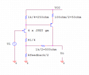
Due to symmetry (you can fold the schematic both along the horizontal and vertical center lines, opposite nodes are at the same potential), the amplifier uses in fact one jfet at the input.
So why is this not a CFA?
The impedance mode at the input.
For CFA this has to be a low impedance, see defenition of CFAs, in the case of J Curl it is high impedance.
Whats all this fuss about this topology anyway, for those that dont understand look at LM6172 literature and replace the BJT diamond buffers with Jfet buffers.
Scott has also shown such a design here in the preamps section.
This is the topolgy used by Krell and the most recent high end Marantz amplifiers, its also my topology of choice for power amps but using BJTs.
As usual, you did not answer any of my legitimate questions. You proved yourself again as one of the masters of statements without any support in reality.
In order to do any apple to apple comparison, one needs to see the at least the amplifiers specifications. One thing I agree, 800W/4ohm is not required in a home, even if one considers the speaker impedance dip, and the phase shift.
I did heard about those transistors, they are certainly good devices, however:
a) they were not available 30 years ago
b) they don't have any SOA data available
c) they are only 150W devices, no temperature power derating is specified
d) they are only 160V devices, can't use them at +/-90V
e) they are specified at Icmax=15A, but no ICmax peak value is given, strange for a power device.
f) they are currently unobtanium.
Except for the larger Ft, these devices seem to be in the same class/process as the 2SC5200/2SA1943 pair, and I think the latter can be used as direct replacements (minus the different casing). The low Cob (200pF compared to 600pF for the onsemi MJL's) makes me think that 2SC2565/2SA1095 are smaller area devices, hence limited in power (Pmax, SOA) handling. Note that for discrete power devices the Cob is, in a first approximation, depending only on the device area and (indirectly) on the breakdown voltage.
I wont even bother with the first half.
Devices such as the 2sa1095 were maybe not available in the UK and USA 30 years ago whose goverments had strong anti japanese import policies but were available in other parts of the world hence your misinformation.
Offcourse they are different to the MJLs, but the fact remains that such devices were available.
Why do I get the feeling that the "violin" Waly used means that he isn't surprised at the results he got. I would be happy with that sort of measured THD at that power especially for a prototype setup. It's a real life measurement and not spice.
Noise?
yes. agree. noise. used in several places, commercially.... such as mixing consoles.
would be interesting in a powr amp app. usually more effective in reducing noise in higher gain areas, though.
-rm
The impedance mode at the input.
For CFA this has to be a low impedance, see defenition of CFAs, in the case of J Curl it is high impedance.
No, it is not. The inverting input node impedance is Rfeedback/2. If the jfet would be replaced by a bipolar (with appropriate changes to the biasing), then the impedance would be approximately Rfeedback/2 || R1/4 which is lower, but not necessary hugely lower.
But the CFA aspect is given by the fact that the open loop gain depends on the feedback network, here OLG~[250ohm/(R1/4+Rfeedback || 500ohm)]/[(Rfeedback+500ohm)/50ohm]. Something that never happens in a VFA.
You really need to learn how to break a feedback network and calculate the feedback network loadings. The equivalent schematic is attached.
Attachments
Last edited:
- Home
- Amplifiers
- Solid State
- CFA Topology Audio Amplifiers