AFAIK, the only sub ppm 20kHz SPICE world designs are Edmond Stuart's and he has some 'real world' confirmation too.
It's not the only one, my TT amp simulate THD20k 0.78ppm at 100 W/8 ohm and 1.36 ppm at 200 W/4 ohm. I don't have real world confirmation, it's playing but never measured THD.
Attachments
Please make experiments of these conditions:
1. Inputs are limited bandwidth but using 2 amp but different slew rate (ex. one amp has 20kHz power bandwidth and the other have 200kHz power bandwidth).
2. Inputs are not limited bandwidth but using 2 amp but different slew rate (ex. one amp has 20kHz power bandwidth and the other have 200kHz power bandwidth).
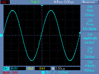
I do not know such a horrible thing like 20kHz power bandwidth, these days. Attached please find easily achieved 65Vpp/100kHz at power amplifier output.
Attachments
Last edited:
I don't have real world confirmation, it's playing but never measured THD.
Try to measure real world THD 20kHz. My guess is it would be 10 times or more worse than the simulated result.
I do not know such a horrible thing like 20kHz power bandwidth, these days. Attached please find easily achieved 65Vpp/100kHz at power amplifier output.
We can easily make amp with 20kHz power bandwidth for experiment.
I want to know if slew rate affected output behavior in amp or not. Right know we think amp slew rate requirement determine by input signal slew rate only.
It is interesting if we can notice which amp that have high slew rate and low slew rate with input limited bandwidth in double blind test.
Last edited:
I am really able to multiply link level output slope with power amplifier gain, and other trivialities mentioned. My point is the real slew rate of music signals. I have done quite a lot of analysis, and the value is pretty low. I also have no problem to build an amplifier with slew rate numbers high enough, yet not sure it is really necessary.
I believe you, and my calculations weren't exact. But if you look at my actual arguments you'll see that I'm talking about distortion caused by RF noise, not by bandwidth problems with the actual musical signal. A 192KHz soundcard is easily able to generate signals that could bring an amp near its BW limit, and they don't have to be of musical origin.
Thanks for the insights kgrlee.
Maybe it's subjective, but in my personal experience I've never heard a system that compares to the accuracy of sitting at a restaurant table with voices all around, or even listening to a car drive past through a window and around a corner. If you want a reference, just sit quiet and listen to what's happening around you. I have once or twice had a setup where I truly could not distinguish between a sound coming from the speakers and from somewhere else, and I'd be looking around for the source of the sound. This is all using the same speakers, just trying different amp designs. If it's in my head, it's a spectacular hallucination. If that's the condition for most of the human race, we are truly, deeply screwed as a species. I don't dismiss that possibility - on the contrary I give it a very high probability. Still, designing super-amps is pretty fun, whether you can hear it or not.
RF noise is a different issue and must be considered, definitely. Then, an effective RF filter at the input (best at input connector) + proper RF case design is a must.
Are "oversized" base stoppers bad design?
Now I am a bit confused - in your book (p194) you wrote:
Decoupling can't be the reason for the instability if base stopper resistors where too low: two different PCB layouts (1st one was using many small decoupling caps and 2nd one is using many small electrolytics) and also the first prototype hand wired shows the same "wiggles".
Even using this "bad design" 18R base stoppers the output stage has a slew rate of ~ 900 - 1000V/µS
Using 2 - 3 pairs of MJL3281/1302 with 2.2R - 4.7R base stoppers using 0.22R emitter resistors seems to be standard here.
But what happens on interaction between 8 pairs of TTC5200/TTA1943 using 0.47R emitter resistors?
Attached a simulation of the output stage only.
"lib" files can be found here: 2stageef-high-performance-class-ab-power-amp-200w8r-400w4r
BR, Toni
...
A designer who needs to use such large base stoppers to avoid HF instability has done a poor job somewhere in the output stage in regard to layout, decoupling, or something else. There are many ways to screw up in this way.
...
Now I am a bit confused - in your book (p194) you wrote:
Sometimes series base resistors are added to promote better stability in the output stage. This is more often the case when several output transistors are connected in parallel. It reduces interactions among the paralleled output transistors that can lead to instability or oscillation.
My 8 pairs paralled OPS with 0.47R emitter resistors show exactly this behaviour and need 15 - 18R base stopper resistors to be stable under all conditions (a second prototype using MJL3281/1302 instead of TTC5200/TTA1943 even need a higher resistor of 22R).
Decoupling can't be the reason for the instability if base stopper resistors where too low: two different PCB layouts (1st one was using many small decoupling caps and 2nd one is using many small electrolytics) and also the first prototype hand wired shows the same "wiggles".
Even using this "bad design" 18R base stoppers the output stage has a slew rate of ~ 900 - 1000V/µS
Using 2 - 3 pairs of MJL3281/1302 with 2.2R - 4.7R base stoppers using 0.22R emitter resistors seems to be standard here.
But what happens on interaction between 8 pairs of TTC5200/TTA1943 using 0.47R emitter resistors?
Attached a simulation of the output stage only.
"lib" files can be found here: 2stageef-high-performance-class-ab-power-amp-200w8r-400w4r
BR, Toni
Attachments
There is only one remaining highest quality mfr of polystyrene specifically for capacitors. It is in China. If you want them, you need to spec them as source to your cap film buyer/mfr. Or, you can save the trouble and get the ps types from REL-CAP in southern california. They will make you the best quality cap with the best film to what ever tolerance you like. Dont expect the leads to fall off or drop out.... but they aint cheap, either. 100% tested. But for .1mfd, the cost is not terrible. Cant buy just 1-2 though from them. They can refer you to a distributor, however. They also make the best audio caps IMHO... I share a patent with them (MultiCap) which takes a custom built cap machine to make them. The owner (Bas Lim) has a PHd in material science... he and I worked out the details of how to make a great cap and those and his standard line are superior.
THx-RNMarsh
Can you point to one or more of the distributers, preferably in europe of the rel-caps.
A couple of months back I was searching for current suppliers and found a little known but high quality manufacturer in germany. Maybe there is more than only the manufacturer in China ??
I prefer and have always used styrene caps for audio. The best examples which Im lucky to still have some stocks of are the philips 1% range from 20 years back.
Now I am a bit confused - in your book (p194) you wrote:Sometimes series base resistors are added to promote better stability in the output stage. This is more often the case when several output transistors are connected in parallel. It reduces interactions among the paralleled output transistors that can lead to instability or oscillation.My 8 pairs paralled OPS with 0.47R emitter resistors show exactly this behaviour and need 15 - 18R base stopper resistors to be stable under all conditions (a second prototype using MJL3281/1302 instead of TTC5200/TTA1943 even need a higher resistor of 22R).
Decoupling can't be the reason for the instability if base stopper resistors where too low: two different PCB layouts (1st one was using many small decoupling caps and 2nd one is using many small electrolytics) and also the first prototype hand wired shows the same "wiggles".
Even using this "bad design" 18R base stoppers the output stage has a slew rate of ~ 900 - 1000V/µS
Using 2 - 3 pairs of MJL3281/1302 with 2.2R - 4.7R base stoppers using 0.22R emitter resistors seems to be standard here.
But what happens on interaction between 8 pairs of TTC5200/TTA1943 using 0.47R emitter resistors?
Attached a simulation of the output stage only.
"lib" files can be found here: 2stageef-high-performance-class-ab-power-amp-200w8r-400w4r
BR, Toni
The best cure for such a situation is the use of a small shunt capacitance to ground from the vas node to lower the vas impedance at high frequencies. Look at commercial designs and see how they cure the problem. D Self has now at last written about it in his latest book.
In this situation you can often get away with a smaller cap if you put a resistor in series with it.
The best cure for such a situation is the use of a small shunt capacitance to ground from the vas node to lower the vas impedance at high frequencies. Look at commercial designs and see how they cure the problem. D Self has now at last written about it in his latest book.
... for 3EF, but this is a 2EF with enhanced VAS.
Using bigger base stopper cures. Using a shunt capacitor (have tried from as low as 33p to as high as 220p) doesn't really help but kills slew rate and increases distortion. Haven't tried ferrite beads yet.
... for 3EF, but this is a 2EF with enhanced VAS.
Using bigger base stopper cures. Using a shunt capacitor (have tried from as low as 33p to as high as 220p) doesn't really help but kills slew rate and increases distortion. Haven't tried ferrite beads yet.
I dont know what the problem is then, a small shunt usually does the job, whether EF or 3EF. This cap is uaually so small one only sees a THD rise above 30 to 40 Khz. Maybe TMC compensation might not be so stable after all ?? I doubt this is a problem youll be able to solve with spice though, it s going to be hands-on sweat. Good luck. Nice looking amp BTW.
I cannot see your circuit, but if you are using an EF3 and you are not taking good care with dampers on the driver bases to the rails, RC decoupled between the driver and pre- driver, plus damper resistor in the pre driver collector lead you are likely to get parasitic oscillation.
Bob Cordell covers this in his book, and OStripper has built a number of EF3's without issue. On my website I have a write up on the e-Amp which is an EF3 VFA and I have no issues. My base stoppers are 4.7 Ohms.
I did many hours of testing and experimentation - EF3's using 30 MHz Ft devices can be problematic if you don't take precautions.
Last edited:
It's an EF2 design. Maybe TMC could cause something like this but I'm not sure. Does it stop if you use another compensation method?
Also, does simulation replicate this or not?
Also, does simulation replicate this or not?
Have you tried the cap with a resistor in series? What frequency is the oscillation?
The frequency is about 5 - 6 MHz good damped - but I don't like it hence the bigger base stoppers. Only at the end of the falling edge.
Maybe I am fooling myself using a bad square wave generator ...
It's an EF2 design. Maybe TMC could cause something like this but I'm not sure. Does it stop if you use another compensation method?
Also, does simulation replicate this or not?
Earlier design has used TPC copmpensation - same behavior. Never seen this in simulation.
Do you have stoppers on the driver bases? Another option is a damper from the driver base to the rails. A small 10 ohm resistor in the collector of the drivers might also help.
The solution is not to have high base stoppers for reasons Bob Cordell covers in his book.
The solution is not to have high base stoppers for reasons Bob Cordell covers in his book.
I dont know what the problem is then, a small shunt usually does the job, whether EF or 3EF. This cap is uaually so small one only sees a THD rise above 30 to 40 Khz. Maybe TMC compensation might not be so stable after all ?? I doubt this is a problem youll be able to solve with spice though, it s going to be hands-on sweat. Good luck. Nice looking amp BTW.
Have tried different shunt caps from 33p - 330p with/without different series resistors. It cures, but kills slew/increases distortion. Only bigger base stoppers are helping regardless of the pcb design / wire amp.
If you add the PCB and trace inductances, you will probsbly get it to oscillate. Figure on 10 nH per cm.
- Home
- Amplifiers
- Solid State
- CFA Topology Audio Amplifiers