I don't think we have conclusive proof that the lower VAS output impeadance accounts for the phase differences noted between CFA and VFA.
The CFA BW advantage is even greater with a MOSFET OPS. I would expect if the real reason for the difference was because of the VAS OP Z then there would be less difference or no difference between CFA and VFA with MOSFET OPS.
What is we use a current mirror second stage for the CFA? Hi OP Z yet that also achieves higher ULGzf for the same phase margin.
The real reason is with fewer gain stages, there's less phase shift in the CFA.
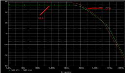
...Both versions have EXACTLY the same gain.
No. The CFA has more open loop gain once roll-off starts, about 3 dB at 10 kHz and increases to 6 dB extra at the end of the plot.
So more loop gain available too.
But this is not a criticism, it is impressive to see a "CFA" with that much gain.
As I said, well worth further study.
Please, do as i did, don't bet, listen 🙂
You wrote "I bet"😉 and I am very ready to listen.
I am quite serious. If there is a real audible difference then I will happily pay for a fine meal to have learnt this.
And if there is no audible difference then a free fine meal will taste very nice.
Best wishes
David
Last edited:
Extracted just the needed models and was able to run the simulation.
I made the bias for the OPS identical, I don't know why it was different in Andrew's attachment.
Once I made the transistors in the VFA match the "CFA" and made the feedback network identical then the hi-frequency differences between them almost vanished.
The "CFA" has open loop 0 dB just above 14 MHz. The VFA just below 13 MHz.
Theory predicts that the OPS pole should be similar so VFA and "CFA" differences should be small.
The results are consistent with theory, in fact the difference is even less than I expected.
Best wishes
David.
I noted virtually no differences between the open loop unity intercept frequency as well - seemy attachment. About 10 MHz in my case.
Look at the phase margins when the loop is closed - that's where you see the differences.
Again, the differences are entirely consistent with what would be expected if phase accumulation between the temp models was different - which they are and easily explainable.
There's no magic here - the results follow theory.
I don't think we have conclusive proof that the lower VAS output impe.dance accounts for the phase differences noted between CFA and VFA...
I still want better proof but it's almost moot now.
Once the transistors, bias and feedback networks were made identical then the hi-frequency responses became very similar and the phase differences are essentially completely explained by the usual amplitude/phase transform.
At least it looks that way, Anyone know how to plot the true "excess phase" that is not due to the minimum phase (Hilbert) transform?
Best wishes
David.
Cross posted with Andrew. Similar conclusions.
Andrew, I see no explanation for the different bias and transistors, it was just mistakes?
Last edited:
IMHO commercial audio amplifier manufacture's would not build CFA based amps if there was not a viable REAL market for them. They have to make a profit. DIYAudio amps will trounce the commercial ones once built and given a chance. DIYAudio Amps are built better, with better components and the best without the restraints of the profit motive.
IMHO commercial audio amplifier manufacture's would not build CFA based amps if there was not a viable REAL market for them. They have to make a profit. DIYAudio amps will trounce the commercial ones once built and given a chance. DIYAudio Amps are built better, with better components and the best without the restraints of the profit motive.
I think it wont be long after this study going on here results in many new commercial designs that are CFA with better performance for same money spent. Real progress.
Is IT only due to Impedances? Expansive Currents? Fewer gain stages? Speed? BW/PM? Or, just all of them working together?
Thx-RNMarsh
Last edited:
I may go one step further and discuss exactly why the VAS output impedance behaves differently for the two topologies.
Here we go again: it will be a tough ride for the "listening crowd" - but I couldn't care less, "ignorance is bliss" 😀.
So the question was, why are the CFA and the VFA VAS output impedances so different? And in particular, why is the CFAoutput impedance higher at LF and lower at HF, resulting in shifting the OPS pole up, when compared to the VFA output impedance?
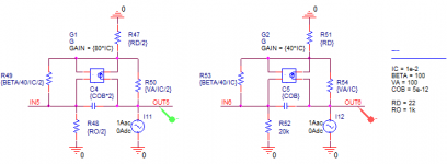
The first step is to recognize the symmetry of the CFA. Assuming ideally matched n/p devices, from an AC perspective we can fold the CFA schematic upper and lower halfs, because symmetrical nodes will always have identical potentials. As a result, we can analyze only the upper half of the schematic, if we double the capacitors, half the resistances and double the transconductances. What we finally get is a double (transconductance) transistor
This is not the case in the VFA VAS. There's no simmetry, so the VAS stage is simply a transistor, having the input fed by the LTP output.
The next step is to draw the equivalent schematics, taking the above symmetry into account and including the other transistor elements we got to the attached schematics. Referring to the VFA schematic on the right, Ic=10mA, gm=40*10mA=0.4S, Beta=100, VA=100V, Cob=5pF. Hence, R53=Rbe=Beta/gm=250ohm, R54=Ro=VA/Ic=10k. Nothe the half and double values in the CFA schematic, due to the mentioned symmetry.
Both VASes are fed by current sources, that are the previous stage transistors. However, here's a first glaring difference. The output impedance of the previous stage is modelled, for the VFA, by a 20k resistor (since current mirror loaded LTP has a high output impedance, could be as high as the LTP transistors Ro/2) while the output impedance of the previous stage is dominated by the 1k resistor (actually 500 ohm due to the simmetry), check Bonsai's schematics.
Now leave the inputs IN5 and IN6 open (for impedance determinations, independent current sources should be left open and independent voltage sources should be shorted) and place the AC current probe at the output. As before, if the probe current is set to 1A, the output voltage is numerically equal to the output impedance. What you get is attached (plotted at log scale).
Here we go: we got the same result as analyzing the full schematic in the previous post. Compared to the VFA, the CFA output impedance is higher at LF and lower at HF, there is a frequency at which those two output impedances are equal. Now we can play with the circuit elements and parameters to find out the root cause.
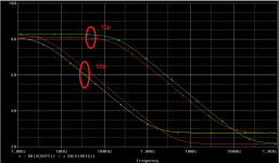
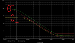
The four parameters are on the schematic. Let's start first with two extreme values for the bias current IC (1mA and 20mA, attached). Short of some LF changes, the output impedances crossing frequency is almost the same; no changes in the HF behavior, which means that the OPS pole will remain approximately in the same position. Again, the CFA has a lower output impedance at HF, meaning that the OPS pole will be higher in frequency.
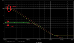
Secondly, let's see what if we select a VAS device with extreme Betas (50 and 1000). Low beta or high beta, the CFA output impedance is always lower at HF. However, for low beta, the crossing frequency doesn't necessary occur. The output impedances are almost identical for the VFA or CFA, until well into the MHZ range. This also means that low beta will provide the same gain at lower frequecies, so the VFA will have the advantage of higher LF gain only for high beta VAS devices. Is this surprising? Not at all, it shows why high beta devices are good for the VAS.
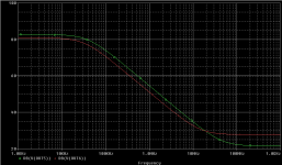
Third, let's see the Early voltage VA effect. Also short of the LF output impedances, the HF behavior of the CFA and VFA is exactly the same; the crossing frequency where the VFA and CFA output impedances are equal does not practically depend on the VA. The CFA will always have a lower HF impedance, meaning the OPS pole will be higher in frequency.
Fourth, let's check the Cob effect (attached). As expected, Cob has an important effect on the crossing frequency, however it does not change at all the HF behaviour. The CFA will always have a lower output impedance.
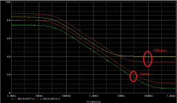
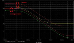
So far, we played with the VAS device parameters only. Let's see now what we get when dealing with the external circuit values: the VAS degeneration and the previous stage output impedance (fror the CFA, the 1k/500ohm resistor in Bonsai's schematic) (attached). Now we really got something interesting and relevant. If no VAS degeneration is used, the CFA output impedance will always be lower than the VAS output impedance, no crossing frequency occurs. If we are using a (high) VAS degeneration, then we got the already known shape, with a crossing frequency, which decreases with increasing the degeneration. Therefore, the lower the degeneration, the more advantageous the CFA topology used here is (stability is not discussed here). We like low VAS output impedance not only because it provides a better frequency response, but also because it provides lower open loop distortions; we already know that the (high) source impedance is a major source of distortions for a bipolar OPS.
And let's see the effect of the 1k/500ohm resistor (attached). Bingo! For low value RO (100ohm) we got the already known effect of lowering the CFA output impedance at HF. But for high RO we got nothing! The CFA and VFA output impedances are practically identical, meaning there's no effect on the OPS pole frequency position!
Now before cheering for this late result, we have to admit that in the CFA topology, RO and RD are not independent. Their ratio sets the VAS bias current, se we'd better see what's happening with the CFA when the RO/RD ratio is constant (attached). The formula to calculate RD as a function of RO is (RO*1e-3-0.7)/1e-2 where 1e-3 is the previous stage bias current and 1e-2 is the VAS bias current. And we hit another jackpot! Obviously, the VFA output impedance doesn't depend on RO. If we want to have the OPS pole pushed higher in frequency (while keeping the input stage and the VAS bias current constant), there is an RO optimum. For RO=100ohm, the CFA VAS output impedance is always much higher than the VFA, so no OPS pole pushing, in fact the OPS pole will be at a lower frequency compared to the VFA! The same happens for large RO values! This is logical, if we think that increasing RO also needs to increase the VAS degeneration, to keep the same VAS bias current. There is only a narrow values for RO to exhibit the OPS pole up frequency shift (around 1k), and Bonsai hit it by chance.
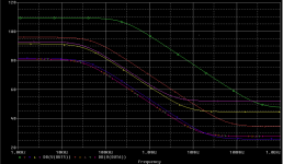
Let's now take the opposite approach, and parametrize RO by RD (attached). We will now have both the CFA and the VFA have variable output impedances, as a function of RD. Surprising or not, the output impedances are crossing only for high degenerations. For low degenerations, the CFA output impedance is always lower than the VFA, which means that the lower the degeneration, the better the frequency response of the CFA will be (again, stability issues are not discussed here). However, lowering the degeneration will also lower the first stage gain (just see waht happens when you put a current generator at the input and determine the gain) which means in fact that we just traded open loop gain for bandwidth, so nothing really surprising.
We are done. Of course, these results may suggest many design improvements, like bypassing (part of) the degeneration at HF, adding a beta enhancer for the VFA, etc... This was actually intended only for showing that the global feedback loop is irrelevant on the frequency behavior of the OPS pole. We did all this analysis under open loop conditions, and got different behaviors depending on the circuit design, in fact we could easily flip the reported OPS pole behavior if we really want to. One thing is certain: Bonsai tried to compare CFA vs. VFA, actually running into such a comparison is irrelevant, useless and misleading (not to mention the CFA acronym which is totally irrelevant). What was compared were two circuit topology which may or may have different properties (for good and for bad), under various conditions. That's not what I call an apple to apple comparison, and in fact there are no such apple to apple metric when comparing these.
And to conclude, attached is the loop gain of the two topologies, if no degeneration is used (with a slight adjustment to the CFA, to keep the same biases in the VAS). As everybody can seen the delta in the frequency response (OPS pole frequency position, etc...) between the CFA and the VFA is almost gone... We just transformed a "CFA" in a "VFA" by modifying one resistor value.
So much for the "current feedback amplifiers for audio"... just a different topology, same-o-same feedback.
Attachments
-
 cfa_vfa_vas.png9.8 KB · Views: 255
 -
 cfa_vfa_output_impedance_RD_param.png16.4 KB · Views: 118
 -
 cfa_vfa_output_impedance_RO_param.png17.2 KB · Views: 116
 -
 cfa_vfa_output_impedance_RD.png19.6 KB · Views: 125
 -
 cfa_vfa_output_impedance_RO.png14.9 KB · Views: 129
 -
 cfa_vfa_output_impedance_COB.png19.3 KB · Views: 114
 -
 cfa_vfa_output_impedance_VA.png17.8 KB · Views: 245
 -
 cfa_vfa_output_impedance_BETA.png15.9 KB · Views: 250
 -
 cfa_vfa_output_impedance_IC.png19.1 KB · Views: 249
 -
 cfa_vfa_output_impedance.png17.2 KB · Views: 259
When i mean exactly the same gain, i refer to 100Hz, where poles have no influences.No. The CFA has more open loop gain once roll-off starts, about 3 dB at 10 kHz and increases to 6 dB extra at the end of the plot.
The open loop BW differences were part of the study.
VAS is (or can be) the same in CFA and if VFA, (as well as OPS). So, what is the point in this noise that i have not read any further ?So the question was, why are the CFA and the VFA VAS output impedances so different?
If you can find a difference in impedances of the (same) VAS, just look where the only difference is: in the previous stage, the input one.
VAS is (or can be) the same in CFA and if VFA, (as well as OPS). So, what is the point in this noise that i have not read any further ?
If you can find a difference in impedances of the (same) VAS, just look where the only difference is: in the previous stage, the input one.
The response is in the first line of my post. Ignore everything I said and have happy listening experiences! No (electronics) knowledge is required to enjoy music.
But a minimum of intelligence is requested to pontificate about electronic.No (electronics) knowledge is required to enjoy music.
The first line of your post "it will be a tough ride for the "listening crowd" - but I couldn't care less, ignorance is bliss" was just one of your usual insults and injuries. And a peak of ridicule, in the same time.
What about your promise to stay away from this thread, with all this crazy listening crowd, witch build amplifiers in the purpose to reproduce music, ô great Guru ?
Last edited:
Extracted just the needed models and was able to run the simulation.
I made the bias for the OPS identical, I don't know why it was different in Andrew's attachment.
Once I made the transistors in the VFA match the "CFA" and made the feedback network identical then the hi-frequency differences between them almost vanished.
The "CFA" has open loop 0 dB just above 14 MHz. The VFA just below 13 MHz.
Theory predicts that the OPS pole should be similar so VFA and "CFA" differences should be small.
The results are consistent with theory, in fact the difference is even less than I expected.
Best wishes
David.
Thanks, Dave. This seems to be a good step in the direction of apples-apples.
Cheers,
Bob
Member
Joined 2009
Paid Member
The only difference between VFA and CFA, as indicated L.C., is the added pole of the emitter follower in the feedback return
I pointed that out some posts ago....
"Andrew, I see no explanation for the different bias and transistors, it was just mistakes?"
Yes I have models of both in the library.
Re bias, they may be a bit different, but I don't think it will change the fundamental conclusions of the analysis.
I will Complete my analysis and then update the article on my website - I need to close this one off 🙂
Yes I have models of both in the library.
Re bias, they may be a bit different, but I don't think it will change the fundamental conclusions of the analysis.
I will Complete my analysis and then update the article on my website - I need to close this one off 🙂
I pointed that out some posts ago....
It has been long before this thread exist. That's why LC called it "back to square one" 😀
Member
Joined 2009
Paid Member
look at the blowtorch thread.....claims and counter claims....they go round and round....i will just build myself an amp or two...😀
kettle, pot?
Shall we count how many times Esperado has railed at statements of objective facts as evidence of of “hate”, has mis attributed/misconstrued opinions, even after several pointers to what has actually been said by those of us discussing what "conventional engineering" has to say about circuit design factors in the technical performance of amps, and when such are not sole attributes of CFA amps, or try to put numbers on the blindly assumed "CFA advantage"?
give up the "fanboy" paranoia, the position that any not confirming/conforming to your position are "attacking" and the thread may proceed more smoothly
and I believe it is well settled diyAudio policy that there are no protected threads/forums for “pure subjectivists” - objective fact, logical reasoning, and personal opinions are allowed in any thread
...was just one of your usual insults and injuries
Shall we count how many times Esperado has railed at statements of objective facts as evidence of of “hate”, has mis attributed/misconstrued opinions, even after several pointers to what has actually been said by those of us discussing what "conventional engineering" has to say about circuit design factors in the technical performance of amps, and when such are not sole attributes of CFA amps, or try to put numbers on the blindly assumed "CFA advantage"?
give up the "fanboy" paranoia, the position that any not confirming/conforming to your position are "attacking" and the thread may proceed more smoothly
and I believe it is well settled diyAudio policy that there are no protected threads/forums for “pure subjectivists” - objective fact, logical reasoning, and personal opinions are allowed in any thread
- Home
- Amplifiers
- Solid State
- CFA Topology Audio Amplifiers