Bonsai pointed out the positive aspects of the CFA.
I've explored the negative aspects in my quest to
build MY own "idiotproof" simple design.
The PSRR is a no brainer - better regulation of the IPS , no way
around it.
I am still concerned about DC stability. With DC coupled FB
(in the real world) ,just blowing on one device in the diamond
would likely produce offset.
Most OEM CFA's use a servo .... Hmmmm
Tightly coupled (face to face)with compound and heatshrinked , I'm sure
they would thermally stabilize.
As the 2 stages change ambient , they cancel each other out.
The Hawksford also negates itself thermally.
Using the big 1000uf DC cap in the FB network (like the NAD) will
equalize small changes in offset. I was mentioned that the cap
will decrease performance .. I'll have to see.
On the other side of the fence , the sansui VFA is a compensation
"nightmare" .... change any aspect of NFB/Re value and a careful
adjustment of the lead/lag components is crucial.
CFA/VFA both have a unique set of compromises. 😀
OS
I don't think it is PSRR. The amp that sound worse is VFA: symetrical, input cascode, VAS cascode, and 3EF.
For the" blameless" (Badger) , the first impression is the "soundstage/detail".
It's topology exhibits the best native PSRR - could be a correlation here.
The hawksford cascode is actually the first "noticeable" VAS I have heard,
as far as improved audio quality. (As compared to a CCS loaded one)
OS
It brings phase turns at LF.Using the big 1000uf DC cap in the FB network (like the NAD) will
equalize small changes in offset. I was mentioned that the cap
will decrease performance .. I'll have to see.
So, reducing the feedback accuracy, increase the distortion several octaves over the FC.
It brings phase turns at LF.
So, reducing the feedback accuracy, increase the distortion several octaves over the FC.
Huh?
Then, let's all work on this aspect to limit the impact under dynamic conditions. Does the MOSFET OPS help in this regard compared to BJT? And, which OPS topology does best in this regard?
Thx-RNMarsh
A properly designed MOSFET output stage should help in this regard. That is partly why I was able to operate my MOSFET EC amp at a ULGF of 2MHz in 1983.
However, MOSFETs are not perfect and laterals are not the same as verticals. The verticals do see increased input capacitance from drain to gate when the signal swings up near the rail. At minimum, this means that the MOSFET should be driven with a fairly low impedance at HF. Normally, verticals have a very high effective ft - often in the hundreds of MHz, much more than even ring emitter BJTs.
Laterals suffer from low transconductance and significant distributed gate resistance, so their performance at HF may not be as good, although they suffer much less in regard to increased drain-gate capacitance when the signal is up near the rail.
All of these considerations likely apply equally to VFA and CFA.
Cheers,
Bob
It brings phase turns at LF.
So, reducing the feedback accuracy, increase the distortion several octaves over the FC.
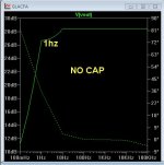
Huh , LT shows the same "everything" with or w/o the cap.
The cap just emulates a "virtual ground". I know how to proceed
either way .. my ears and DMM will tell the truth.
OS
Not sure I follow. What is "output zero"? Of course one noise source cannot be uncorrelated with itself.
I meant, "little sense for fighting the Early effect". Otherwise, of course the cascade is always helping with cancelling the Miller effect in the lower common emitter device (and with isolating the output from the input). From a distortion perspective, both the lower device nonlinear Miller cap and the upper common base Early voltage are important.
Hi Waly,
I guess I wrote a sentence that was somewhat unclear. It meant that the transfer from the noise source to the output ideally becomes zero.
I disagree with your statement about Early effect. Even when the cascode device has a terribly low output resistance, a common-emitter stage with cascode on top still has a much higher output resistance than a plain common-emitter stage. Just as long as the cascode has a voltage and a current gain much greater than one. If you don't believe me, do the math or ask a simulator.
Best regards,
Marcel
CFA unreliable? From Pioneer to Marantz to Sony.... for decades -- have used the CFA topology for its reliability, ease of compensation/stability and great specs and sound quality. For decades. This is not just a high-end tweak-o idea. It is a well established technology in many applications. Especially, audio and for mass produced products.
Thx-RNMarsh
Thx-RNMarsh
Last edited:
Sorry, no schematic with your post: i thought it was about a DC blocking cap between feedback bridge and ground.Huh , LT shows the same "everything" with or w/o the cap.
The cap just emulates a "virtual ground". I know how to proceed
either way .. my ears and DMM will tell the truth.
Hi Waly,
[..]
I disagree with your statement about Early effect. Even when the cascode device has a terribly low output resistance, a common-emitter stage with cascode on top still has a much higher output resistance than a plain common-emitter stage. Just as long as the cascode has a voltage and a current gain much greater than one. If you don't believe me, do the math or ask a simulator.
Best regards,
Marcel
Marcel, you are perfectly right!
Bonsai pointed out the positive aspects of the CFA.
I've explored the negative aspects in my quest to
build MY own "idiotproof" simple design.
I am still concerned about DC stability. With DC coupled FB
(in the real world) ,just blowing on one device in the diamond
would likely produce offset.
Most OEM CFA's use a servo .... Hmmmm
Tightly coupled (face to face)with compound and heatshrinked , I'm sure
they would thermally stabilize.
As the 2 stages change ambient , they cancel each other out.
The Hawksford also negates itself thermally.
Using the big 1000uf DC cap in the FB network (like the NAD) will
equalize small changes in offset. I was mentioned that the cap
will decrease performance .. I'll have to see.
On the other side of the fence , the sansui VFA is a compensation
"nightmare" .... change any aspect of NFB/Re value and a careful
adjustment of the lead/lag components is crucial.
CFA/VFA both have a unique set of compromises. 😀
OS
dc offset with temp changes do not have to be an issue with careful design... and low gain power amp circuits, the drift is minor. Otherwise, a servo is more reliable and more perfect than a 1000mfd electro cap. but, if determined to use a 1000mfd cap... make it a bipolar and 105C.
IF, you let your devices run warm compared to ambient, any ambient changes in the home will have very minimal temp change affect to device...... thermally more stable.
THx-RNMarsh
Last edited:
Hi Waly,
I guess I wrote a sentence that was somewhat unclear. It meant that the transfer from the noise source to the output ideally becomes zero.
I disagree with your statement about Early effect. Even when the cascode device has a terribly low output resistance, a common-emitter stage with cascode on top still has a much higher output resistance than a plain common-emitter stage. Just as long as the cascode has a voltage and a current gain much greater than one. If you don't believe me, do the math or ask a simulator.
Yes you are right, the common base output impedance is about Beta times larger than a common emitter output impedance.
About the noise, I still have to think about. I'm still not convinced it would correctly model the noise transfer function. Indeed, a single noise source added to, say, the power supply would have an output (or input referred) contribution divided by the PSRR (so as much as the hum contribution). Trouble is, such noise sources are never alone, and they are never ideal generators. To identify that particular current noise source contribution to the total noise is not straightforward.
Thanks for the heads up.
Sorry, no schematic with your post: i thought it was about a DC blocking cap between feedback bridge and ground.
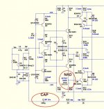
Schema below , NAD does the offset and cap the same way.
I also looked at the NAD layout for any thermal considerations.
The NAD's VAS runs "hot" (big heatsink), mine is at 4.5ma.
I also have Bonsai's NX as reference (DC w/ trimmer on NFB).
I left the option open for NO cap (true ground ref.) for FB divider.
I know there will be a V1.1 😀.
PS - lucky for me , just a 75mm sq. fr-4 PCB , won't have to "scrap" the OPS.
OS
Attachments
Last edited:
dc offset with temp changes do not have to be an issue with careful design... and low gain power amp circuits, the drift is minor. Otherwise, a servo is more reliable and more perfect than a 1000mfd electro cap. but, if determined to use a 1000mfd cap... make it a bipolar and 105C.
IF, you let your devices run warm compared to ambient, any ambient changes in the home will have very minimal temp change affect to device...... thermally more stable.
THx-RNMarsh
OK , as far as the Cap ... I will use a 1Kuf /25V BP panasonic (105C).
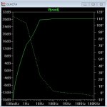
Another aspect of the DC vs. CAP issue.
DC gives me a 1hz rolloff ... "rumble" - I don't use vinyl .. 😀
The CAP rolls off at about 10 hz , about the same as a VFA with my
standard 220uF blocker.
I could easily run my diamond/2'nd stage at 2+ mA , as you suggest.
I use 1.6mA because this is where the 1845/992's have lowest THD.
2-2.5mA is real close .... just a couple ppm.
OS
Attachments
So, try a sim with 1Farad, and compare distortion at 100Hz with your 0.1FSchema below
OPS interaction with CFA.
It was mentioned about many variable poles on the OPS changing
with load.
http://www.diyaudio.com/forums/solid-state/149324-self-type-3-ef-hybrid-triple-any-pointers-2.html
As I remember , by making the drivers as high Ft in an EF3 , they determine
the pole.
I tried different driver models , the toshiba 2sc4793/sa1837 pair work the best.
Both my OEM's (HK/Sansui )use them ,as well as most other EF3's on the consumer market.
with MJExxxx as driver ... while some VFA sims fail - the CFA will still
work. I do not trust this false security.
A fast predriver (like the KSA/C's) also exhibit this behavior.
The OEM's use "slow" predrivers , often 2SB/2SDxxxx (under 30mhz Ft)
and 100mhz Ft drivers.
Sanken and ON outputs are mostly 30mHz Ft.
So , the almost universal trend is 30/60-100/30Mhz. For my big TO-3p
drivers ... I will go for the Sanken 2sc2837/sa1186 (70mHz).
OS
So, try a sim with 1Farad, and compare distortion at 100Hz with your 0.1F
Thanks , I usually don't concentrate on LF THD. You are correct !
DC= .004%
1F = .005%
1000uF = .01%
At about 500hz everything becomes equal again (20-25 ppm) .
Another drawback of CFA. VFA does not do this.
Edit- VFA DOES do this (but not as much - .005%100hz from 5ppm 10khz).
DC NFB has purpose.
😕
OS
Last edited:
Improving system sound is an iterative process: many setups start to sound "not so good" at relatively low SPLs, so the listener never ventures beyond certain volumes, there's a "safe" level that the user doesn't want to pass, it brings in "unpleasantness". But, improving something then suddenly allows that volume level to be increased - the car can go 10mph faster without feeling like it will fly off the road going around that bad corner, 😀.I don't think it is PSRR. The amp that sound worse is VFA: symetrical, input cascode, VAS cascode, and 3EF.
However, two things have now happened - the extra volume means that extra information can be heard in the recording ... and some of that doesn't sound quite right; and, the system now working 'harder' means that areas that weren't quite as 'stressed' as before are now starting to misbehave, to the point of introducing different audible artifacts. So, perversely, the better a system gets the more work usually needs to be done to refine to the next level of quality; the finer the qualities one is capable is achieving with the components at hand, the more effort is needed to actually realise those behaviours.
Think Formula One cars - capable of staggering performance ... but the slightest misalignment or issue completely throws the abilities of the beast to do well; only the constant fiddling by engineers and mechanics is able to keep the car's edge where it needs to be. And at the moment this is also true of audio, IME ...
You got it. And, you've had it for quit some time.... other's just needed it explained or demonstrated in many different ways and by several designs/designers until it gets across.... which i think it is, now. I found that if you tell people something that isnt explained in sufficient detail, you just get arguments and disbelief most of the time.... so you point the way and let them learn that way. Some can lead them to water but ---.
😎🙂
-Richard Marsh
Hi Richard,
Not so fast; I'll await Bonsai's reply to my question.
I suppose you think I'm one of those "unwashed" who is slow to get it, and have to have it explained many different ways. That's OK. That's the way I am 🙂.
Perhaps YOU can explain to me why it is OK to operate with a ULGF greater than the OPS pole with a CFA, while it is not OK to do it with adequate margin with a VFA.
I'm trying to get to the core of the issue in this very good, but very noisy thread.
Cheers,
Bob
I learn how to improve slew rate and THD in amp design. But I still do not understand how to improve intermodulation distortion. Please some one can explain to me with simple words?
You could find some answers here. 😉
Why 2 amp with almost same THD can sound differently, especially in high frequency? I use same input and same speaker. One amp sound more detail in high frequency.
One amp has TLF (The Leakage Factor) greater then the other. This new expression will find its way in audio circles from now on more frequently. It cannot be simmed, measured yes.

- Home
- Amplifiers
- Solid State
- CFA Topology Audio Amplifiers