Whose done this here?
-RM
I would likely do it if i could see it would work.
But we are talking CFA here!? Where is IN-??? Where is the feedback loop to be placed?
- Sonny
PS: But i would make I1 and I3 slave of I2. Maybe reduce the current translation between I2:I1 10:1.... But it would certanly help getting the idle current in the Transistors connected to I1 les modulated.
Last edited:
at best its a variation on "replica cancellation - where you are "copying" the load current, "adding" its effect back in a Class A stage
these characteristics make for some difficulty in translating the principle to Class AB output power amp with varying Z with frequency, noticeable nonlinearity in voice coil heating, inductance modulation...
All types are difficult until you work it thru and solve the issues. This and/or other cancellation techniques free up designer to optimize circuit parameters which are otherwise limited in 'traditional' means.
And, frequently, fewer parts are needed. Stability issues are not degraded and may be simplified.
How would you do it?
Thx-RNMarsh
Last edited:
How would you do it?
well I think I can get most of what's needed by human audio perception limits, or transducer, recording/playback accuracy with negative feedback
but if you want to "play" - how about Pass SuSy?
I would likely do it if i could see it would work.
But we are talking CFA here!? Where is IN-??? Where is the feedback loop to be placed?
- Sonny
PS: But i would make I1 and I3 slave of I2. Maybe reduce the current translation between I2:I1 10:1.... But it would certanly help getting the idle current in the Transistors connected to I1 less modulated.
To all---- try apply this triple-mirror example in your circuits --- see if there is anything else you can lift or use or adapt:
View attachment 3x mirror.pdf
Thx-RNMarsh
Last edited:
well I think I can get most of what's needed by human audio perception limits, or transducer, recording/playback accuracy with negative feedback
but if you want to "play" - how about Pass SuSy?
What would You do for a cancellation design? Or how to configure the Dimitri concept into a symmetrical, complimentary cancellation circuit?
Thx-RNMarsh
Last edited:
Have the preceding eleven posts anything to do with optimizing a diamond IPS, or is nobody interested in this subject?🙄
Please, post the schematic. ThxHow could we configure the distortion cancellation method shown by Dimitri (Elect Design Jul 19, 2012) into a complimentary amp circuit?
Thx-RNMarsh
There's a link in post 3600Please, post the schematic. Thx
CFA -
yes, of course, interested.... we are multi-tasking 🙂 there are several parts -- IPS, OPS and everything in between to discuss. Not in any particular order.
And several excellent CFA designs completed or still evolving.
Thx-RNMarsh
Have the preceding eleven posts anything to do with optimizing a diamond IPS, or is nobody interested in this subject?🙄
yes, of course, interested.... we are multi-tasking 🙂 there are several parts -- IPS, OPS and everything in between to discuss. Not in any particular order.
And several excellent CFA designs completed or still evolving.
Thx-RNMarsh
yes, of course, interested.... we are multi-tasking 🙂 there are several parts -- IPS, OPS and everything in between to discuss. Not in any particular order.
And several excellent CFA designs completed or still evolving.
Thx-RNMarsh
I'm "digesting" post #3135 now.
"Oh where, oh where... to put them diamond collectors"😀
Noise goes down , yes... THD/slew stays the same. But , I lose
6db of PSRR taking the diamond collectors from the emitters of stage 2 -
(versus using the fixed 15v or 33v zener reference).
I show both "flavors" below. 1 is my original ,2'nd is attachment 2
modification from post 3135.
Edit - had to adjust Q5/6 currents as the diamond current is added to this stage now.
OS
Attachments

Last edited:
So? BTW, your modification is NOT according to post 3135. The resistor values (RE and Rfb) are very critical, of course.
I did add the cascodes as well ... and tried many Re's. A cfa is a cfa ...
I suppose I was looking for a "silver bullet" - none found.
Everything worked .... no bad enginneering. But no "bullet".
OS
I suppose I was looking for a "silver bullet" - none found.
Everything worked .... no bad enginneering. But no "bullet".
OS
"Of course one could calculate analytically the proper values of the emitter resistors, but as I am lazy, I used my simulator to figure it out, though it's an iterative process.
In the example below, Ic of the output trannies (Q3 & Q4) were set to 1mA. So for lowest distortion RE2 should be: 0.5 * VT / Ic = 13 Ohms. Check this as shown in fig.1."
This something like how I got to 15 Ohms in my nx and sx amps for RE.
In the example below, Ic of the output trannies (Q3 & Q4) were set to 1mA. So for lowest distortion RE2 should be: 0.5 * VT / Ic = 13 Ohms. Check this as shown in fig.1."
This something like how I got to 15 Ohms in my nx and sx amps for RE.
Ostripper, I wonder what would happen if you split the FB network an inject it where you connect the diamond, and then let the degeneration resistors be the backside of the feedback with the center point tied to the DC blocking cap. Then you would actually also inject sone feedback into the input diamond
Ostripper, I wonder what would happen if you split the FB network an inject it where you connect the diamond, and then let the degeneration resistors be the backside of the feedback with the center point tied to the DC blocking cap. Then you would actually also inject sone feedback into the input diamond
Tried that , too ... It does increase slew , as does ES's 2'nd circuit.
I tied the collectors of the diamonds to:
1. The fixed zeners (12 -33V)
2. A point between the 2'nd stage and a set of cascodes
3. The CF point (like you suggested).
4. Even to the CCS collectors.
ALL 4 worked well , giving the same 20K 10-20ppm 1/2 power THD.
PSRR descended from #1 to #4
Denon , Marantz , and NAD all have patents on the "base" circuit like
the ones I posted or the NX.
NAD's 372 is a close match for mine. this CFA hoopla is 20 years old ...
I'm surprised so few projects have taken so long to appear 😕 .
I should of listened to apex ... who dropped some examples on this thread.
Looking at how the OEM units are designed and how long they lasted -
The 372's are almost a decade old , all still work (no design issues) .. some
of the older Marantz CFA's are being recapped and sold as "vintage" on ebay.
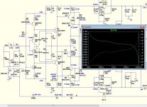
Also simulated the marantz MA9S2 (below) with wilson CM loaded Hawksford.
NO "silver bullet".
You would not believe all the marketing hype CFA was given - "hyper current drive".. blah blah .. 🙄
etc.
BTW - the VSSA/peeceebee are simplified variants of older marantz's.
Now I know how to build 'em !! (OEM examples).
OS
Attachments

Also simulated the marantz MA9S2 (below) with wilson CM loaded Hawksford.
NO "silver bullet".
OS
This is NOT MA9S2! MA9S2 has some special features, which are missing from this chineese copy. The sound quality of this version is far away from the original Marantz, unfortunately.
Sajti
The resistor values (RE and Rfb) are very critical, of course.
The question is the feedback network sets the ULGF (My personal limit is 1Mhz) but can you set the compensation network (VAS shunt and 2 pole miller) to override this, is this a problem?
BTW, tried Waly's mod to the cfp version of the diamond buffer and the only gain I got was less output offset. THD stayed almost exactly the same.
PS. Can't post schematic as home computer needs a motherboard change which should arrive today.
I know Cordell likes THD 20 kHz as a quick test but I think it could be misleading, shows "high loop gain" in poor light compared to what we know about human hearing
20-20kHz "conventional audio" really is THE most important range, hearing sensitivity falls off really fast as you approach the limits
so a "bad" 100ppm THD 20k may say little about actual audible consequences
I prefer 2-tone IMD, looking for in "conventional audio" band IMD products, usually with high amplitude 1:1 20 kHz sine and a lower frequency probe sine that gives easily calculated nth order difference products in the conventional audio band that can be easily viewed in FFT
of course this is where high loop gain negative feedback excels - because excess loop gain reduces any error - including IMD products by the (high) excess loop gain/"feedback" at the error frequency
- Home
- Amplifiers
- Solid State
- CFA Topology Audio Amplifiers