I fail to see what higher order comp schemes are going to bring to the party. We've been over this low distortion thing ad neauseum and I feel it's simply led nowhere.
More importantly, we should spend time and effort on construction, wiring, layout, power supply, decoupling and so forth.
Just my two cents worth and hope I've not trodden on any toes.
It is always good to push the limits and see what will happen. In that case this CFA discussion and design has shown that impressively low distortion IS possible with CFA. One of the many CFA myths busted.
Construction is, of course full of issues, and almost every amp ever designed here at DIYAUDIO has something to say about it. Even over on the Blowtorch/JC discussions it is talked about for what must be years in the making.
What new issue can be explored in the construction means and methods that has not also been covered to adnosium?
Perhaps, the specific parts related to wideband circuits would apply for CFA.
Thx-RNMarsh
Happy New Year, Richard.
These are good points. Class D has come a long, long way.
One thing to keep in mind is that class D has made deep inroads into the home in the form of AV receivers. Most of those 5.1 and 7.1 channel receivers you buy have class D output stages in them. And for good reason: how else could you get 7 75-watt power amplifiers in a reasonably-sized and priced AV receiver without the use of class D?
Of course, there is a significant distance in SQ target from AV receiver to audiophile amplifiers driving audiophile speakers.
Cheers,
Bob
It is not the performance of Class D that has allowed this directly to be applied to receivers. The reduced weight, size and cost of heat sink area and transformers to handle - in analog fashion - the multi-channel power is the driving force to incorporate Class D.
In my context, the performance is not there yet.... esp at lower output levels. Though quit good for the price. But packing a lot of power in a small/light weight space is there... and selling Watts make profits, too.
Thx-RNmarsh
Last edited:
Yes , class D COULD be made good , but this not the driving force behind
development.
99$ - 5.1 channel appliances at Walmart is where the $$ are.
This was going on 30 years ago ... I wondered why the Sansui VFA has
130-150db PSRR. This is so they could use a dirt cheap PS. They even
"stole" the non-critical 15V supply for the power amp from the preamp to
save on a zener/transistor.
You add real PS's and real regulators to some of these decades old
circuits - and you have real high end amplification.
OS
Member
Joined 2009
Paid Member
You add real PS's and real regulators to some of these decades old
circuits - and you have real high end amplification.
Funny you should mention this !!! I was thinking of trying this myself. I have a new/modern HT receiver but as usual, the power supply is not that strong and short on capacitance. I've simulated the amplifier and it looks like a good design. All it needs is a good power supply.
Hi,
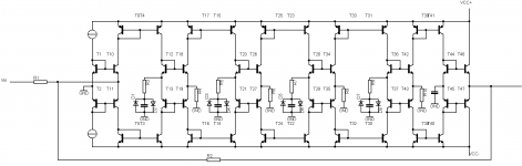
Useful or not, I've made a little sketch of an amplifier with fifth-order compensation, class-AB behaviour in each stage and feedback to the emitters of the input stage, just to make sure it is on topic. I've left out a lot of details, as I just wanted to illustrate the concept. I have no idea if it can be made to work in practice, it is just a wild idea.
Basically, it is a standard controversial feedback amplifier, drawn in inverting configuration, with four extra gain stages in between. Each extra stage has an integration capacitor that sets the pole, a series resistor to make a frequency-compensation zero and two clipping diodes to limit the capacitor voltage under large-signal conditions, thereby effectively reducing the order.
One could start in a simulator with replacing all capacitors except the last one with short-circuits and trying to get it stable with a decent margin. Once that is done and the achievable unity loop gain bandwidth is known, you can insert the capacitors and make their value such that the RC product with the series resistor is 10/(2*pi*f_unityloopgain). Each stage then adds a phase shift of about -5.7 degrees, so with four stages you loose 22.8 degrees of phase margin. Experiment a bit with the actual values.
Once it is small-signal stable, large signal stability has to be checked. Do the diodes kick in early enough to make it recover from overload or from a bad initial state? If not, scaling down the capacitance and scaling up both resistors (series resistor of the capacitor and emitter resistor) in each stage might help.
The bit that worries me the most is the phase shift of the current mirrors, especially when you add emitter resistors to reduce the matching requirements. Maybe you can add emitter resistors and shunt them with relatively big capacitors. A folded cascode would be nicer, but spoils the AB-/current-on-demand behaviour of the intermediate stages.
Best regards,
Marcel
Attachments
Poor energy storage and delivery is probably the issue in most units. Tried a "cheap and nasty" commercial Japanese receiver in a store, driving a very efficient Klipsch unit with benign load characteristics - and that beat the pants off most so-called high end systems, in terms of real dynamics, while retaining decent quality of sound ...Funny you should mention this !!! I was thinking of trying this myself. I have a new/modern HT receiver but as usual, the power supply is not that strong and short on capacitance. I've simulated the amplifier and it looks like a good design. All it needs is a good power supply.
It is not the performance of Class D that has allowed this directly to be applied to receivers. The reduced weight, size and cost of heat sink area and transformers to handle - in analog fashion - the multi-channel power is the driving force to incorporate Class D.
In my context, the performance is not there yet.... esp at lower output levels. Though quit good for the price. But packing a lot of power in a small/light weight space is there... and selling Watts make profits, too.
Thx-RNmarsh
Also the sound, nowadays class AB are just horrible, young designers are lost their ears and brighten their eyes. For example is LA4440 and LA4445 are sounded better than new chips. Here local company just move to classD because class AB is also horrible.
Class D have to find their ways with self oscillating. Variable caps also available to be placed in classD to achieve junction capacitive effect (that enhance some good class AB sound). Just imagine when classD people start to use their ears😀 and class AB people use their eyes😉.
It is always good to push the limits and see what will happen. In that case this CFA discussion and design has shown that impressively low distortion IS possible with CFA. One of the many CFA myths busted.
Thx-RNMarsh
I got 0.6ppm 20k with buf diamond input.
Attachments
Quite a few designs on this thread have demonstrated single digit distortion levels at 20 kHz at high powers, and sub 1 ppm at mid to low powers. I fail to see what higher order comp schemes are going to bring to the party. We've been over this low distortion thing ad neauseum and I feel it's simply led nowhere.
More importantly, we should spend time and effort on construction, wiring, layout, power supply, decoupling and so forth.
Just my two cents worth and hope I've not trodden on any toes.
Not mine.. sir ,
 .
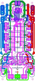
.I've been doing just that. Your advice on the FB placement was helpful.
The Halcro DM58 goes one step further and "floats" the NFB through the
AIR with a stiff silver wire ! I've incorporated this in the "slewmaster OPS"
(below). Stiff copper wire (arrow in middle) 1" off the board , right angle ..
strait to the heart of the CFA IPS "daughter card". This wire will be 18ga
with a UV reactive teflon sheath - Hawksford UV led's will provide for the
"alien" look 😱 .
Mr. Candy also "floats" OPS inductor away from the amps PCB
as well with shielding..... I won't get that anal 😀 .
Grounding is dual star (dirty/clean-G1/2) , this also could be "floated"
with the atmosphere being used as an insulator 😎 ... no capacitance
or inductance in air. 😀
Ended the "dirty ground" right at the driver stage , cap multipliers reference to
G2 (clean).
Now to the IPS's ....
PS - I'll get my PPM's one way or another.
OS
Attachments
😎🙂
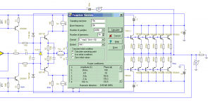
Hmmmm. Well, I suggested only two in cascade. This is OTTop. What does a Mr. SIM think of this? What does fewer stages do this way?
Thank you for trying to find out what can be obtained by cascading current mirrors.
Thx-RNMarsh
Hmmmm. Well, I suggested only two in cascade. This is OTTop. What does a Mr. SIM think of this? What does fewer stages do this way?
Thank you for trying to find out what can be obtained by cascading current mirrors.
Thx-RNMarsh
Hi,
Useful or not, I've made a little sketch of an amplifier with fifth-order compensation, class-AB behaviour in each stage and feedback to the emitters of the input stage, just to make sure it is on topic. I've left out a lot of details, as I just wanted to illustrate the concept. I have no idea if it can be made to work in practice, it is just a wild idea.
Basically, it is a standard controversial feedback amplifier, drawn in inverting configuration, with four extra gain stages in between. Each extra stage has an integration capacitor that sets the pole, a series resistor to make a frequency-compensation zero and two clipping diodes to limit the capacitor voltage under large-signal conditions, thereby effectively reducing the order.
One could start in a simulator with replacing all capacitors except the last one with short-circuits and trying to get it stable with a decent margin. Once that is done and the achievable unity loop gain bandwidth is known, you can insert the capacitors and make their value such that the RC product with the series resistor is 10/(2*pi*f_unityloopgain). Each stage then adds a phase shift of about -5.7 degrees, so with four stages you loose 22.8 degrees of phase margin. Experiment a bit with the actual values.
Once it is small-signal stable, large signal stability has to be checked. Do the diodes kick in early enough to make it recover from overload or from a bad initial state? If not, scaling down the capacitance and scaling up both resistors (series resistor of the capacitor and emitter resistor) in each stage might help.
The bit that worries me the most is the phase shift of the current mirrors, especially when you add emitter resistors to reduce the matching requirements. Maybe you can add emitter resistors and shunt them with relatively big capacitors. A folded cascode would be nicer, but spoils the AB-/current-on-demand behaviour of the intermediate stages.
Best regards,
Marcel
Member
Joined 2009
Paid Member
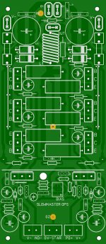
Not mine.. sir ,
I've been doing just that. Your advice on the FB placement was helpful.
The Halcro DM58 goes one step further and "floats" the NFB through the
AIR with a stiff silver wire ! I've incorporated this in the "slewmaster OPS"
(below). Stiff copper wire (arrow in middle) 1" off the board , right angle ..
strait to the heart of the CFA IPS "daughter card". This wire will be 18ga
with a UV reactive teflon sheath - Hawksford UV led's will provide for the
"alien" look 😱 .
Mr. Candy also "floats" OPS inductor away from the amps PCB
as well with shielding..... I won't get that anal 😀 .
Grounding is dual star (dirty/clean-G1/2) , this also could be "floated"
with the atmosphere being used as an insulator 😎 ... no capacitance
or inductance in air. 😀
Ended the "dirty ground" right at the driver stage , cap multipliers reference to
G2 (clean).
Now to the IPS's ....
PS - I'll get my PPM's one way or another.
OS
Can not wait for this CFAmp to also get built and tested and listened to. This should help start building a consensus on the designing, performance and listening of another very good CFAmp.
-RM
Last edited:
Trouble is ... sometimes being 'anal' is exactly what's required to solve a problem - everything else one does is skirting the issue, like trying to move a stone by pushing it with a stick that's 10 feet long - sometimes, the best solution is to just get in there and move the bloody stone by picking it up in your bare hands!! ... 😀Mr. Candy also "floats" OPS inductor away from the amps PCB
as well with shielding..... I won't get that anal 😀
PS - I'll get my PPM's one way or another.
OS
PPM distortion seems useless😀 or you may need to buy some silver inductor😉.
Can not wait for this CFAmp to also get built and tested and listened to. This should help to start to build a consensus on the designing, performance and listening of another very good CFAmp.
-RM
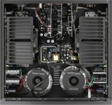
The CFA deserves the BEST OPS ! I own a HK680 (e waste ! ) and have had
the pleasure of a HK990 (below 1) in the man cave.
The $500 HK680 is more "mid-fi" construction. But ...It's bias spreader is
highly accurate.
The $2500 HK990 is the "ultimate triple" !!! 1 Thermaltrak pair + 4 pair MJLxxxx + hawksford VAS (below 2).
For DIY , using T-tracks and a super sensitive 4 device Vbe would frighten
some builders , but the 990's PCB design and VAS was the "cats meow" 🙂
So .. it was a compromise between the 2 designs.
I know some don't like EF3's , but they have many more benefits than
drawbacks.
The IPS's can be miniaturized (even SMD'ed) , as everything can be run
at 1-5mA. All 3 of my designed IPS's run with 12-15ma per rail.
On the (corrected) OPS board (below 3) , there is even enough room
for a "failsafe" LOCKDOWN on the bias spreader if the IPS is disconnected.
Any ideas on this ?
OS
Attachments

Trouble is ... sometimes being 'anal' is exactly what's required to solve a problem - everything else one does is skirting the issue, like trying to move a stone by pushing it with a stick that's 10 feet long - sometimes, the best solution is to just get in there and move the bloody stone by picking it up in your bare hands!! ... 😀
Mr. Candy uses RF level devices/layout and claims the DM is SUB ppm ! He did what he needed to achieve those design goals.
I read he "borrows" tech from his metal detector business to design amps.
PS - my goal is to at least preserve the majority of the simulated performance from these CFA designs.
OS
Last edited:
The CFA deserves the BEST OPS !The $2500 HK990 is the "ultimate triple" !!! 1 Thermaltrak pair + 4 pair MJLxxxx + hawksford VAS (below 2).
For DIY , using T-tracks and a super sensitive 4 device Vbe would frighten
some builders , but the 990's PCB design and VAS was the "cats meow" 🙂
, there is even enough room
for a "failsafe" LOCKDOWN on the bias spreader if the IPS is disconnected.
Any ideas on this ?
OS
Have you run sim on the thermal tracking? Any desire to try FET in OPS? And, if so, how would the Thermal-tracking need to work/modifiy with them?
Thx-RNMarsh
Last edited:
Have you run sim on the thermal tracking? Any desire to try FET in OPS? And, if so, how would the Thermal-tracking need to work with them?
Thx-RNMarsh
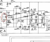
Yes , my in home HK680 is "real world" thermal tracking sim 😀. I have only simulated
the IPS's to determine what gets thermally coupled on the IPS boards.
Here's how the 2 transistor Vbe works ... HK matched each of the 2( Hfe wise)
to the stage that is being tracked.
HK uses 2sc4793/2sa1837 for drivers on a separate HS with a 2sc3423-y Vbe.
I have considered my using the lower Hfe NJWxxxx for the driver stage.
Use either a lower gain driver Vbe .... or trim R442-444 (schema below) to
change the driver Vbe coefficient.
The output stage , like on the Badger ... I built it , then trimmed
the main Vbe C - B resistor to tweak the tracking. This is better than simulation.
I've really built both the Hawksford and many standard VAS's. I put both on
a small piece of aluminum flashing (like the badger). On the Hawksford
, the to-92 active devices also are thermally coupled to the VAS HS.
Edit - the hawksford's 4 transistors thermally cancel each other out ...
I simulated the input stages ( ksa992/sc1845) on my CFA's. They are
more sensitive to changes than a typical VFA.
Both the first 2 stages of the NX and the VSSA input stage MUST be coupled.
I most likely will couple all 4 !!! of the NX TO-92's together.
The LED CCS's are quite stable and I expect no "bad behavior" from them.
I DON'T like FET's .... "mosfet mist" ha ha ....
PS - with laterals fet's , just a simple resistor and a safety zener is all that
is needed for thermal stability
OS
Attachments
Last edited:
Not mine.. sir ,
I've been doing just that. Your advice on the FB placement was helpful.
The Halcro DM58 goes one step further and "floats" the NFB through the
AIR with a stiff silver wire ! I've incorporated this in the "slewmaster OPS"
(below). Stiff copper wire (arrow in middle) 1" off the board , right angle ..
strait to the heart of the CFA IPS "daughter card". This wire will be 18ga
with a UV reactive teflon sheath - Hawksford UV led's will provide for the
"alien" look 😱 .
Mr. Candy also "floats" OPS inductor away from the amps PCB
as well with shielding..... I won't get that anal 😀 .
Grounding is dual star (dirty/clean-G1/2) , this also could be "floated"
with the atmosphere being used as an insulator 😎 ... no capacitance
or inductance in air. 😀
Ended the "dirty ground" right at the driver stage , cap multipliers reference to
G2 (clean).
Now to the IPS's ....
PS - I'll get my PPM's one way or another.
OS
Very nice layout! Looking forward to seeing the results from this in the next few weeks! I like the idea of the separate cable for the feedback signal.
- Home
- Amplifiers
- Solid State
- CFA Topology Audio Amplifiers