Just a gentle reminder to all that THD sims with MOSFETs without EKV models are seriously fairy-land. Guru Cordell deals at length with this in his book. Measures that reduce distortion, particular cancellation techniques are most badly affected.
Good point, although the stealth circuit seems to be based on negative feedback rather than cancellation. By the way, I know from experience that MOS level 11 models (from NXP/Philips) are also quite good, but I don't know if any cheap simulator supports them.
Scott Wurcer wrote "EDIT - BTW I agree on several other points. It is trivial to add a diamond buffer plus resistor to a "CFA" to get a slew on demand input. So say you pick a closed-loop gain and a resistor and comp cap for the same closed-loop BW. You are designing discrete amplifiers for a fixed application and you have access to everything. The resulting CFA vs VFA comparison would show little difference in performance in the direct signal path. I would look elsewhere, PSRR, CMRR, EMI for differences."
I agree with this. You have to comp to cater for the OPS, so in a classic CFA vs MC VFA you get exactly the same loop gain response above the -3 dB bandwidth. SR is another matter, but MIC etc can get you a good result in VFA.
I agree with this. You have to comp to cater for the OPS, so in a classic CFA vs MC VFA you get exactly the same loop gain response above the -3 dB bandwidth. SR is another matter, but MIC etc can get you a good result in VFA.
You guys are still at it, amazing. The above statement is inaccurate, as I pointed out mikeks. All the current that charges the comp cap and makes the voltage at the gain node move MUST flow in the inverting input. Grounding the inverting input and looking at the open-loop transfer (rougly related to the gm and Cc in the same way as a VFA) is a relatively pointless construct. See any number of EE texts (such as Gray and Searl Electronic Principles, Physics, Models, and Circuits 1969 pages 660-661) for the extraction of a and f for the feedback equation (Ao/1+af) for the simple emitter feedback doublet. The feedback network is considered part of the forward transfer and the input is the voltage between the plus input and ground not the voltage between the base and emitter.
So maybe we should just stop calling it an op-amp.
EDIT - So I see we agree on something maybe, Things are the same but different, A contains terms from the feedback network in one case but not the other. So in one case the feedback network can modify the closed-loop BW. Think about an 8 legs where the user has no access to the frequency compensation, is this just a marketing trick or a useful differentiating feature to the user?
Yes it did, it could be modeled like this one. Its just feed forward amplifier. Actually an emitter of bjt or source of fet are outputs, not an input of a gaining amplifier. The true inputs are bases and gates.
Attachments

vlasinalin
Is it CFA?
Of course CFA
I think that after the resistors R13, R15 should include filtering capacitors of 1000 uF
Resistors R22, R30 connected to the ground rather than on the output
Petr
Is it CFA?
Of course CFA
I think that after the resistors R13, R15 should include filtering capacitors of 1000 uF
Resistors R22, R30 connected to the ground rather than on the output
Petr
Just a gentle reminder to all that THD sims with MOSFETs without EKV models are seriously fairy-land. Guru Cordell deals at length with this in his book. Measures that reduce distortion, particular cancellation techniques are most badly affected.
Which SPICE are you using?Good point, although the stealth circuit seems to be based on negative feedback rather than cancellation. By the way, I know from experience that MOS level 11 models (from NXP/Philips) are also quite good, but I don't know if any cheap simulator supports them.
I don't quite understand ,
I used a wilson current mirror VAS , driven by a basic
CFA.
I removed all compensation .... and it is stable !
The circuit is the same , except for the wilson.
very strange ?? 😕
What is the source of the 3kHz time constant in the response? That would be compensating the closed-loop response. I have seen many VFA's compensated by the device parasitics at higher closed-loop gains.
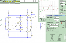
What do you think about the following modified version of Apex AX17?
THD at 20khz with 30V output is 0.004%, SR about 120V/us.
LG phase margin is 80 degree, but, from the OLG bode plot is seems to be unstable, is there a problem in the schematic design?
Is it CFA?
Thank you!
PCB-s are already made, construction is next 😀
It is too complex for 0.004% THD
This simple thing has 0.0087% THD20k in classB, not AB.
Attachments
What do you think about the following modified version of Apex AX17?
THD at 20khz with 30V output is 0.004%, SR about 120V/us.
LG phase margin is 80 degree, but, from the OLG bode plot is seems to be unstable, is there a problem in the schematic design?
Is it CFA?
Thank you!
PCB-s are already made, construction is next 😀
That's like the first one i did.
I notice the tian probe UG/phase is exact to the middlebrook bode I
just posted (DADOD!).
Without a separate front end PS or large cap multiplier PSSR will
suck ("be in the doghouse").
Vbe for that triple will work , don't expect any precision.
Sansui Z3900 has that Vbe, starts at 40ma, goes to 80+ma jammin' 😀,
will settle to 60 after a while - NOT precision.
C4/5 are excessive , 22-47p is better.
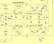
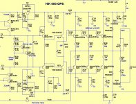
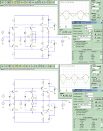
An example- 2 known OPS's ....
below-
1. sansui Z3900 - 32 years old , very reliable. drivers on separate HS.
2. Harmon/kardon 680 - 20 years old , very reliable ... they were running
paralleled car audio speakers ! 😱 off of this , fried a channel. 1mv Vbe accurate.
Separate driver HS with it's own Vbe.
I own both these (found in trash) , they work for decades.
It seems to be a cfa for your IPS , looking at the bode
OS
Attachments
It is too complex for 0.004% THD
This simple thing has 0.0087% THD20k in classB, not AB.
😎🙂
Last edited:
It is too complex for 0.004% THD
This simple thing has 0.0087% THD20k in classB, not AB.
Those "old models" will always be on the optimistic side.
OS
Optimistic ....
Using perfect current sources instead of modeled ones (semi's) , perfect
voltage sources will always inflate performance.
A small amplitude output will always be better (below -..006%@ 100k!) .
"hammer" the thing (amp) .. 2R load + 100V p-p
You might be closer to the" real thing" ...
Is this not the purpose of all the simulation in the first place , to predict
what the prototype will behave like ?
BTW - love my new "toy" (wilson +CFA) ... same currents from CCS to VAS -
fast as lightning. 😀
OS
Attachments
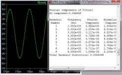
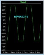
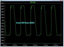
it's all in the models ...
#1. is mpsa92/42 , you would be lulled into bliss 😀 .
#2 is the more realistic fairchild/cordell model , same overdrive.
YUK ! lookin' " dirty" .
trust not the included models on these simulators ...
OS
#1. is mpsa92/42 , you would be lulled into bliss 😀 .
#2 is the more realistic fairchild/cordell model , same overdrive.
YUK ! lookin' " dirty" .
trust not the included models on these simulators ...
OS
Attachments
Those "old models" will always be on the optimistic side.
OS
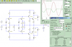
It is class B, only 9mA idle current at OPS, and TIP31/32 bjt. If you change your OPS with 9mA biased TIP31/32, it may (your wilson) won't match this transistor matching stage speed performance. (just sim fun)
0.01%THD@100kHz and 0.06%THD@500kHz
Attachments
Optimized version, 0.0044% THD 20k. 0.0060% THD 100k, match your wilson 😀 may be it will get lower and lower with better matching.
Attachments
Last edited:
It is class B, only 9mA idle current at OPS, and TIP31/32 bjt. If you change your OPS with 9mA biased TIP31/32, it may (your wilson) won't match this transistor matching stage speed performance. (just sim fun)
0.01%THD@100kHz and 0.06%THD@500kHz
Your key statement was "just sim fun" .
Even the "badger" does not do PPM THD (really) . It simulates at ppm ,
hook it to an AP and you get .008 -.01%.
I did not do my wilson for "uber low" THD. I wanted stability , the
ability to slew across a 100V+ in a uS , and to run a 3R load.
It seems you also notice that these CFA's can get respectable THD
at 100K and beyond . I think it is really cool ... 😎
OS
As they slew faster than the equivalent VFA, as their open loop bandwitdth can go up to one oct higher (they request less hf compensation), they behave better at HF for HD and PRRS.YIt seems you also notice that these CFA's can get respectable THD
at 100K and beyond . I think it is really cool ... 😎
But all this, we knew it. Time now to build prototypes and report real measurements and listening impressions. Because it is all About.
Just remember CFAs are more demanding for good PB design and quality of some components (Lytics, FB resistances).
Last edited:
You need to make sure that your ULGF is consistent with sufficient phase margin. If you set the ULGF for say 1.5 MHz on a CFA and VFA to cater for the OPS pole, the loop responses are remarkably similar - both loop (above the -3 dB BW) and closed loop response.
#1. is mpsa92/42 , you would be lulled into bliss 😀 .
#2 is the more realistic fairchild/cordell model , same overdrive.
YUK ! lookin' " dirty" .
trust not the included models on these simulators ...
OS
That's actually quite interesting to me.
On a particular amplifier I built the measured clipping was nice and clean, even with gross overdrive. When I simulated the circuit with models from Farichild (KSA1220AY / KSC2690AY) you'd be led to believe that the rail sticking would be so bad that just touching the rail would be the kiss of death. But reality was actually better than the simulation.
I compared the model from Fairchild to models that behaved well from Cordell and found that Fairchild included many parameters that Cordell did not make use of. So I made a copy of the Fairchild models and removed some of the parameters so that the models contained the same parameters Cordell's models use while leaving Fairchild's values intact. The result was much closer to reality than the model as provided by Fairchild suggested.
Tells me you can't necessarily trust any model until you see it behave the same in simulation as it does in reality.
That's why I use -
ksa992/ksc1845
ksa1381/ksc3503 (the fairchild ones)
njw0281/0302
mjl4281/4302 (Cordell)
zetex (various)
For my bjt amps. These , I have seen have the same saturation on a
scope. They also emulate static operating points within a couple %.
I even went to the point of simulating my sansui and HK amps .... to
the ohm/pF. Upon measuring these OEM's , everything was not only
similar ... but nearly exact. (they both use japanese 2sa992/2sc1845).
Compensation wise , my interpretation of a bode plot can get me within
5pF of where the real amp's zoble will warm up/or Vbias will become
unresponsive (oscillation).
Yes , the 1220/2690 "exaggerates" saturation. I don't use them.
OS
It depend of how fast are your power devices (BJT, FET) and other stages.You need to make sure that your ULGF is consistent with sufficient phase margin. If you set the ULGF for say 1.5 MHz on a CFA and VFA to cater for the OPS pole, the loop responses are remarkably similar - both loop (above the -3 dB BW) and closed loop response.
My way is to tune Miller for flat response in HF (no peak), parallel cap with feedback resistance for no overshoot on little square waves.
All those CFAs/VFAs behavior differences are shown here: http://www.esperado.fr/temp/VSSA/vssa-vs-vfa.html
- Home
- Amplifiers
- Solid State
- CFA Topology Audio Amplifiers