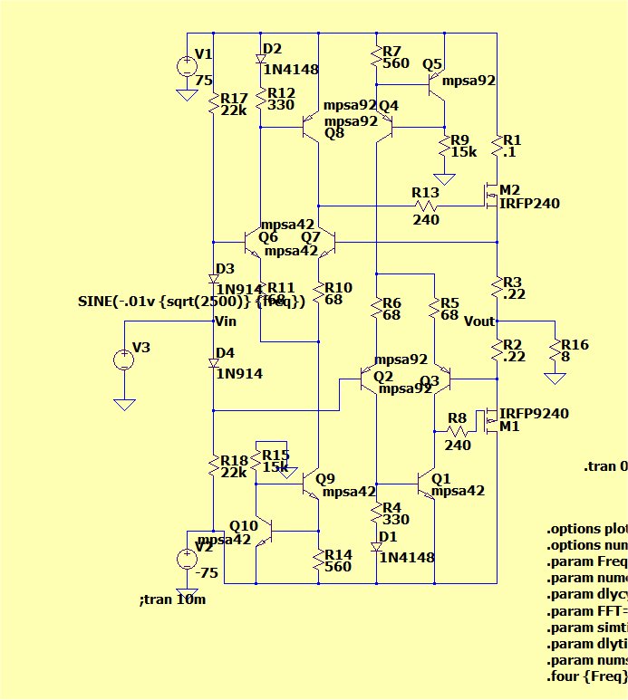
Just a gentle reminder to all that THD sims with MOSFETs without EKV models are seriously fairy-land. Guru Cordell deals at length with this in his book. Measures that reduce distortion, particular cancellation techniques are most badly affected.Here's the stealth , must be "magic" going on.
Really is .004% , same setup as the EF2/3.
(sim and circuit below)
Guru Edmond posted some EKV models but this SPICE newbie can't quite figure out how to use them in LTspice. 😕
_________________
Can we please have less "yus guys are all idiots & deaf" posts? If you think something is in error, explain why in detail. If you can't be bothered to do this properly, don't post at all.
Otherwise all you do is increase the noise and promote even more noise & bickering.
Surely all of us are grown-up and don't need to emulate MikeK? 🙂
Ask before you post, "Am I helping anyone ?"
If you want an examplar, try Guru Bob Cordell. It's obvious that he sometimes disagrees with the views spouted here but his replies are always polite AND USEFUL. A true gentleman and useful too 🙂
Last edited:
if you search you will find I use, recommend CFA quite often
you only damage your credibility by resorting to bad rhetorical tricks, (mis)labeling, strawman - continually attacking any skeptical comment as coming from evil naysayers – seems like your projecting your methods on others
you only damage your credibility by resorting to bad rhetorical tricks, (mis)labeling, strawman - continually attacking any skeptical comment as coming from evil naysayers – seems like your projecting your methods on others
A push-pull Schlotzaur.
The simple Shlotzaur's circuit is described in Self's book "Small signal audio design" page 80.
I tested it with 0.3 W bipolar transistors, the current mirror being of the Wilson 3 devices kind.
Measured distortion is extremely low.
An externally hosted image should be here but it was not working when we last tested it.
Last edited:
Guru Edmond posted some EKV models but this SPICE newbie can't quite figure out how to use them in LTspice. 😕
I've tried them and never been patient enough the let the SIM finish. I'm talking hours for four cycles @ 1khz. Seemed to be working OK tho.
Just a gentle reminder to all that THD sims with MOSFETs without EKV models are seriously fairy-land. Guru Cordell deals at length with this in his book. Measures that reduce distortion, particular cancellation techniques are most badly affected.
Guru Edmond posted some EKV models but this SPICE newbie can't quite figure out how to use them in LTspice. 😕
_________________
Can we please have less "yus guys are all idiots & deaf" posts? If you think something is in error, explain why in detail. If you can't be bothered to do this properly, don't post at all.
Otherwise all you do is increase the noise and promote even more noise & bickering.
Surely all of us are grown-up and don't need to emulate MikeK? 🙂
Ask before you post, "Am I helping anyone ?"
If you want an examplar, try Guru Bob Cordell. It's obvious that he sometimes disagrees with the views spouted here but his replies are always polite AND USEFUL. A true gentleman and useful too 🙂
Yes , "guru" Bob is most gracious to put up with all the childish bickering
while explaining in easy to understand language - "non-condescending rapport".
I did try the class A stealth using ON semi/Cordell BJT models with some
modifications. It really is lower THD than an EF2/3.
In a real world amp , I've seen tests to show the THD >.1% for EF2/3
An LT simulation would be considered "optimistic".
It does not actually "LIE" - but it is not real. The REAL silicon is
not modeled exactly.
In the article below ,it shows the stealth OPS ...
Designing a low-distortion audio output stage - Part 1: Introduction, the problem with push-pull outputs | EDN
It could be used for a CFA OPS (with cheap common BJT's)
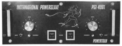
Then there is the "powerslave" (class I ??) OPS ...
http://www.epanorama.net/sff/Audio/Circuits/Power_amplifiers-linear/International%20200W%20Powerslave%20Amplifier.pdf
There we go , more things to "play with" ... 😀
OS
"Moses" comes from the Hebrew verb meaning "to pull/draw out"
Me thinks the Moses OStripper is on the path "to pull/draw out" the CFA goodies/circuit working of course.
Thanks OStripper

Me thinks the Moses OStripper is on the path "to pull/draw out" the CFA goodies/circuit working of course.
Thanks OStripper
The page from Electronics Today International could have been taken straight out of Popular Electronics as for it layout and schematic drawing, style etc. Wow.
The "holy grail" ??
Is this what we want for a OPS ?
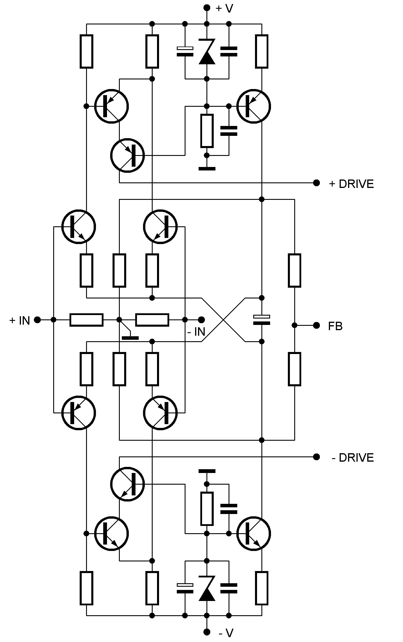
Part 2 of the article - The Class i low-distortion audio output stage (Part 2) | EDN
...describes this topology further. Actually it is simple ... the non-active
half of the class B OP turns into a current source with a fixed value .
This needs to be "simmed" (oooh .. a class I "doublet" )
)
Sounds impressive.
OS
It is possible to dimension a circuit that not only essentially eliminates both the switching and transconductance modulation components of crossover distortion, but also works out of the box in production, over temperature, with absolutely no need for any trimming components or complicated control loops.
Is this what we want for a OPS ?
Part 2 of the article - The Class i low-distortion audio output stage (Part 2) | EDN
...describes this topology further. Actually it is simple ... the non-active
half of the class B OP turns into a current source with a fixed value .
This needs to be "simmed" (oooh .. a class I "doublet"
)Sounds impressive.
OS
EF3 is .04-.05% thd20, regardless of load. EF2 is the same at 8R ... gets worse with load.
Class A genesis stealth OPS is .001%.
Xover dist. is 95% of the THD. That is why Class A has a "following" and
all those OEM's pursue "non-switching OPS's".
OS
It needs only 12dB NFB to reach 0.01% unhearable THD, you could use some jfet.
It needs only 12dB NFB to reach 0.01% unhearable THD, you could use some jfet.
That was the point ... typical EF THD is not too bad.
That is what voltage or current feedback is all about.
Mr. Marsh triggered my interest in the OPS. If we can refine IT ,
we will need less FB. Some report this is more "musical", (low or NO) FB
designs .... who knows ? Could just be a subjective view or personal preference.
I just finished the article (class I- part 2) ,
There is a part 3 with the actual circuit (bottom of part 2 - last page).
I'm about to "wet my feet" .. 😀
PS - if we can eliminate Xover dist. AND the Vbe at the same time - real cool!!
OS
Here is a short summary of CFA and VFA feedback modes.
Hopefully this will clear any remaining confusion up about the 4 canonical feedback modes and the 2 amplifier topologies - CFA and VFA.
I'll clean it up a bit more and put it up on the website in the next few days.
😎
Hopefully this will clear any remaining confusion up about the 4 canonical feedback modes and the 2 amplifier topologies - CFA and VFA.
I'll clean it up a bit more and put it up on the website in the next few days.
😎
Attachments
Member
Joined 2009
Paid Member
Hey, great link to the ETI magazine, took me way back, 1978 ! and only 45p !
Never mind that amplifier, I see a Commodore PET computer - wow, a real blast from the past 😀
Some of those circuits look very similar to the SKA GB150 too.
Never mind that amplifier, I see a Commodore PET computer - wow, a real blast from the past 😀
Some of those circuits look very similar to the SKA GB150 too.
Last edited:
Hey, great link to the ETI magazine, took me way back, 1978 ! and only 45p !
Never mind that amplifier, I see a Commodore PET computer - wow, a real blast from the past 😀
Some of those circuits look very similar to the SKA GB150 too.
Do not tell me you did not notice the Escaping Scantily clad Chica on the front panel of the Amp...😀😀😀

Member
Joined 2009
Paid Member
Do not tell me you did not notice the Escaping Scantily clad Chica on the front panel of the Amp...😀😀😀
I thought that was the schematic 😀
Nice. One little remark i already made: Nothing impeach to implant a balanced input (high Z inverting input) in a CFA.Here is a short summary of CFA and VFA feedback modes.
Like this one from Lazy Cat:
Last edited:
Agree - thats why I call them pointers and not 'tests' in my document. ADI have an op-amp that uses an 'H' input structure to provide CFA like behavior with hi Z inputs.
If the CL -3dB is GBW not constrained and the peak TIS current is determined by the feedback resistor value and not a current source, its almost certainly a CFA.
Why do you think the diagram you show in your post above is a CFA?
If the CL -3dB is GBW not constrained and the peak TIS current is determined by the feedback resistor value and not a current source, its almost certainly a CFA.
Why do you think the diagram you show in your post above is a CFA?
Is this what we want for a OPS ?
Part 2 of the article - The Class i low-distortion audio output stage (Part 2) | EDN
...describes this topology further. Actually it is simple ... the non-active
half of the class B OP turns into a current source with a fixed value .
This needs to be "simmed" (oooh .. a class I "doublet"
Sounds impressive.
OS
OS, we are going again in circle, we have discused non switching OPS here: http://www.diyaudio.com/forums/solid-state/202684-class-i-siblings.html
It still with crossover distortion at HF, because the loop response are too slow with 4 stage transistor for its correction loop. While a cross-management only using 2 stage transistor loop and modify its output signal instead of modify OPS input signal also work better and with applicablility in quasi OPS.
Both nonswitching are useless in sound quality improvement, just for someone looking for fun.
Both nonswitching are useless in sound quality improvement, just for someone looking for fun.
- Home
- Amplifiers
- Solid State
- CFA Topology Audio Amplifiers